WALLMOUNT CONFIGURATION
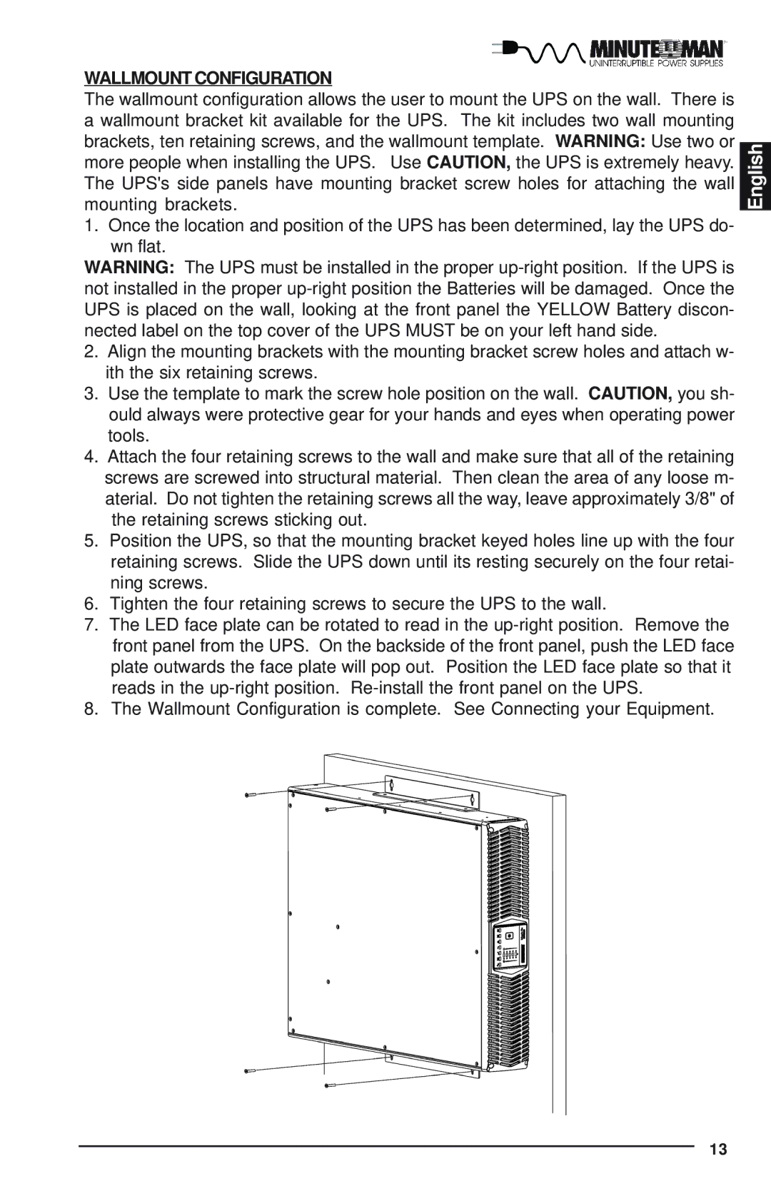
The wallmount configuration allows the user to mount the UPS on the wall. There is a wallmount bracket kit available for the UPS. The kit includes two wall mounting brackets, ten retaining screws, and the wallmount template. WARNING: Use two or more people when installing the UPS. Use CAUTION, the UPS is extremely heavy. The UPS's side panels have mounting bracket screw holes for attaching the wall mounting brackets.
1. Once the location and position of the UPS has been determined, lay the UPS do- wn flat.
WARNING: The UPS must be installed in the proper
2.Align the mounting brackets with the mounting bracket screw holes and attach w- ith the six retaining screws.
3.Use the template to mark the screw hole position on the wall. CAUTION, you sh- ould always were protective gear for your hands and eyes when operating power tools.
4.Attach the four retaining screws to the wall and make sure that all of the retaining screws are screwed into structural material. Then clean the area of any loose m- aterial. Do not tighten the retaining screws all the way, leave approximately 3/8" of the retaining screws sticking out.
5.Position the UPS, so that the mounting bracket keyed holes line up with the four retaining screws. Slide the UPS down until its resting securely on the four retai- ning screws.
6.Tighten the four retaining screws to secure the UPS to the wall.
7.The LED face plate can be rotated to read in the
8.The Wallmount Configuration is complete. See Connecting your Equipment.
English
13