REAR PANEL
English
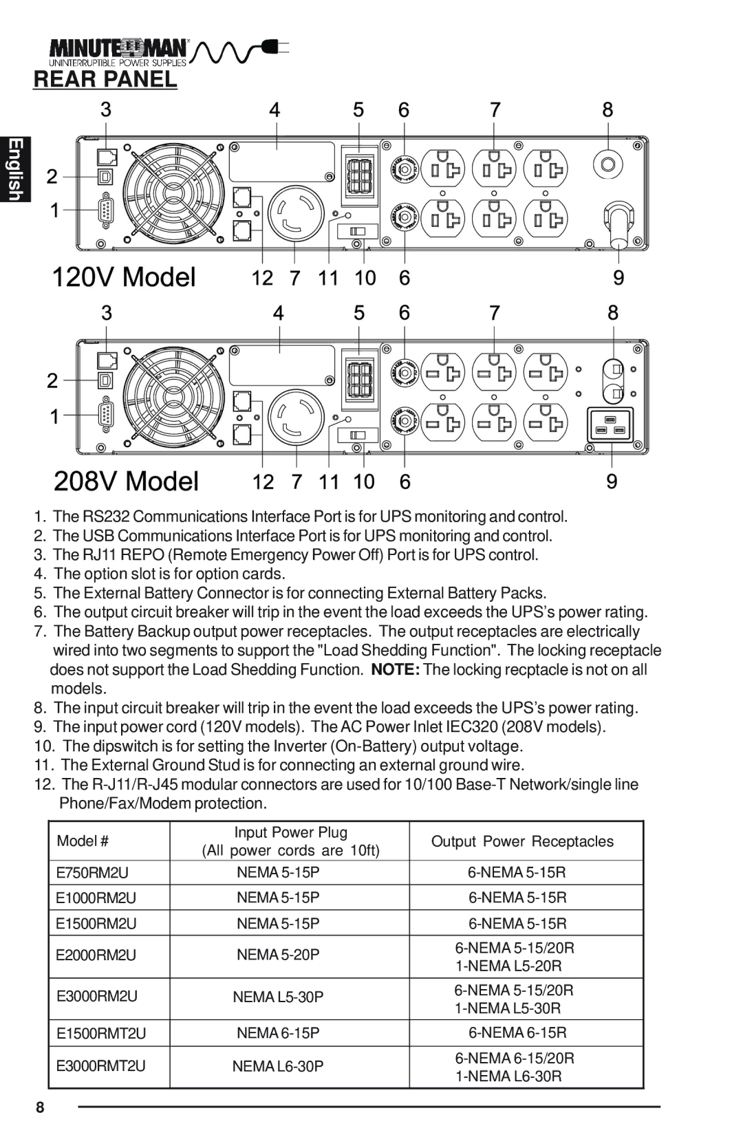
1.The RS232 Communications Interface Port is for UPS monitoring and control.
2.The USB Communications Interface Port is for UPS monitoring and control.
3.The RJ11 REPO (Remote Emergency Power Off) Port is for UPS control.
4.The option slot is for option cards.
5.The External Battery Connector is for connecting External Battery Packs.
6.The output circuit breaker will trip in the event the load exceeds the UPS’s power rating.
7.The Battery Backup output power receptacles. The output receptacles are electrically wired into two segments to support the "Load Shedding Function". The locking receptacle does not support the Load Shedding Function. NOTE: The locking recptacle is not on all models.
8.The input circuit breaker will trip in the event the load exceeds the UPS’s power rating.
9.The input power cord (120V models). The AC Power Inlet IEC320 (208V models).
10.The dipswitch is for setting the Inverter
11.The External Ground Stud is for connecting an external ground wire.
12.The
Model # | Input Power Plug | Output Power Receptacles | |
(All power cords are 10ft) | |||
|
| ||
E750RM2U | NEMA | ||
|
|
| |
E1000RM2U | NEMA | ||
|
|
| |
E1500RM2U | NEMA | ||
|
|
| |
E2000RM2U | NEMA | ||
|
| ||
|
|
| |
E3000RM2U | NEMA | ||
|
| ||
E1500RMT2U | NEMA | ||
|
|
| |
E3000RMT2U | NEMA | ||
|
| ||
|
|
|
8