GUIDE TO INSTALLATION AND OPERATION

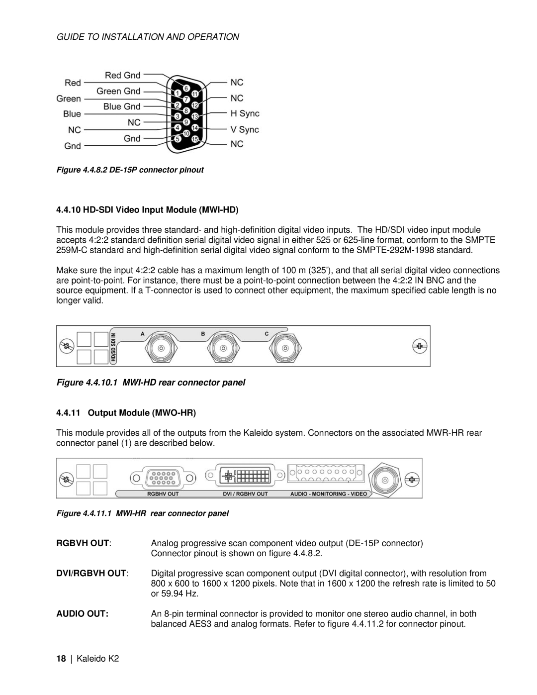
Figure 4.4.8.2 DE-15P connector pinout

4.4.10 HD-SDI Video Input Module (MWI-HD)

This module provides three standard- and high-definition digital video inputs. The HD/SDI video input module accepts 4:2:2 standard definition serial digital video signal in either 525 or 625-line format, conform to the SMPTE 259M-C standard and high-definition serial digital video signal conform to the SMPTE-292M-1998 standard.

Make sure the input 4:2:2 cable has a maximum length of 100 m (325’), and that all serial digital video connections are point-to-point. For instance, there must be a point-to-point connection between the 4:2:2 IN BNC and the source equipment. If a T-connector is used to connect other equipment, the maximum specified cable length is no longer valid.

Figure 4.4.10.1 MWI-HD rear connector panel

4.4.11 Output Module (MWO-HR)

This module provides all of the outputs from the Kaleido system. Connectors on the associated MWR-HR rear connector panel (1) are described below.

Figure 4.4.11.1 MWI-HR rear connector panel

RGBVH OUT: Analog progressive scan component video output (DE-15P connector) Connector pinout is shown on figure 4.4.8.2.

DVI/RGBVH OUT: Digital progressive scan component output (DVI digital connector), with resolution from 800 x 600 to 1600 x 1200 pixels. Note that in 1600 x 1200 the refresh rate is limited to 50 or 59.94 Hz.

AUDIO OUT: An 8-pin terminal connector is provided to monitor one stereo audio channel, in both balanced AES3 and analog formats. Refer to figure 4.4.11.2 for connector pinout.

18 Kaleido K2

Page 22
Image 22
Miranda Camera Co M406-9900-402, KALEIDO-K2 specifications HD-SDI Video Input Module MWI-HD, Output Module MWO-HR