Specifications (continued)
Specification of RGB signals in each computer mode of the projector
Signal mode | Resolution | Horizontal | Vertical | Normal mode | Real mode | |
| (H x V) | frequency (kHz) | frequency (Hz) | (H x V)*1 | (H x V) | |
TV60, 480i (525i) | - |
| 15.73 | 59.94 | 1280 x 720 | - |
TV50, 576i (625i) | - |
| 15.63 | 50.00 | 1280 x 720 | - |
1080i 60 (1125i 60) | - |
| 33.75 | 60.00 | 1280 x 720 | - |
1080i 50 (1125i 50) | - |
| 28.13 | 50.00 | 1280 x 720 | - |
480p (525p) | - |
| 31.47 | 59.94 | 1280 x 720 | - |
576p (625p) | - |
| 31.25 | 50.00 | 1280 x 720 | - |
720p 60 (750p 60) | - |
| 45.00 | 60.00 | 1280 x 720 | - |
720p 50 (750p 50) | - |
| 37.50 | 50.00 | 1280 x 720 | - |
PC98 | 640 x | 400 | 24.82 | 56.42 | 1152 x 720 | 640 x 400 |
CGA70 | 640 x | 400 | 31.47 | 70.09 | 1152 x 720 | 640 x 400 |
VGA60 | 640 x | 480 | 31.47 | 59.94 | 960 x 720 | 640 x 480 |
VGA72 | 640 x | 480 | 37.86 | 72.81 | 960 x 720 | 640 x 480 |
VGA75 | 640 x | 480 | 37.50 | 75.00 | 960 x 720 | 640 x 480 |
VGA85 | 640 x | 480 | 43.27 | 85.01 | 960 x 720 | 640 x 480 |
SVGA56 | 800 x | 600 | 35.16 | 56.25 | 960 x 720 | 800 x 600 |
SVGA60 | 800 x | 600 | 37.88 | 60.32 | 960 x 720 | 800 x 600 |
SVGA72 | 800 x | 600 | 48.08 | 72.19 | 960 x 720 | 800 x 600 |
SVGA75 | 800 x | 600 | 46.88 | 75.00 | 960 x 720 | 800 x 600 |
SVGA85 | 800 x | 600 | 53.67 | 85.06 | 960 x 720 | 800 x 600 |
XGA60 | 1024 x 768 | 48.36 | 60.00 | 960 x 720 | - | |
XGA70 | 1024 x 768 | 56.48 | 70.07 | 960 x 720 | - | |
XGA75 | 1024 x 768 | 60.02 | 75.03 | 960 x 720 | - | |
XGA85 | 1024 x 768 | 68.68 | 85.00 | 960 x 720 | - | |
MAC13 | 640 x | 480 | 35.00 | 66.67 | 960 x 720 | 640 x 480 |
MAC16 | 832 x | 624 | 49.72 | 74.55 | 960 x 720 | 832 x 624 |
MAC19 | 1024 x 768 | 60.24 | 75.02 | 960 x 720 | - | |
HP75 | 1024 x 768 | 62.94 | 74.92 | 960 x 720 | - | |
SXGA60 | 1280 x | 1024 | 60.02 | 63.98 | 900 x 720 | - |
*2
*2
*2
*2
*2
*2
*2
*1: When ASPECT in the FEATURE menu is set to AUTO and SCREEN SIZE in the IMAGE menu is set to16:9.
*2: Available for the signal for the HDMI IN terminal.
Important:
•Some computers aren’t compatible with the projector.
•The projector’s maximum resolution is 1280 x 720 pixels. It may not display images of higher resolutions than 1280 x 720 correctly.
•If the resolution and frequency of your computer aren’t shown on the table, find the compatible resolution and frequency by changing the resolution of your computer.
•In the case of XGA, the right side of the image may not appear. In this case, adjust TRACKING in the SIGNAL menu.
•TV60 and TV50 are equivalent to 480i and 576i respectively. When these signals are supplied to the VIDEO IN or
•This projector doesn’t support video devices having 4 lines (R, G, B, CS*), and 480i, 576i and 480p signals from video devices having 5 lines (R, G, B, H, V).
* : Composite Sync
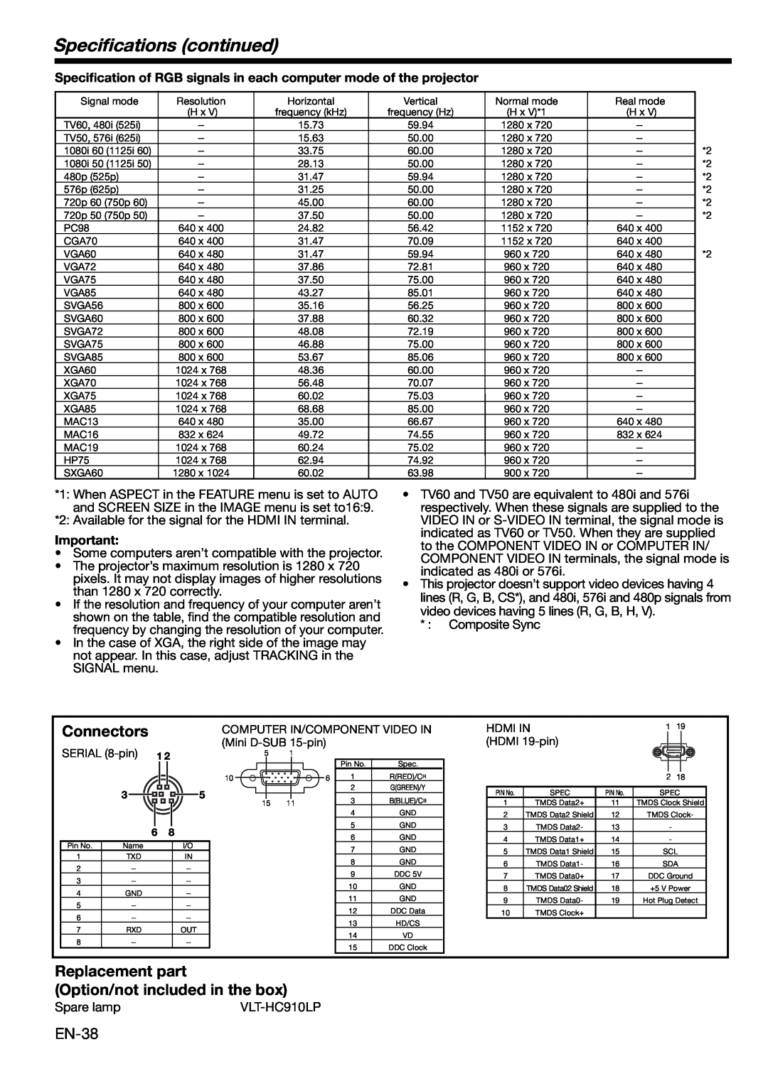
Connectors
COMPUTER IN/COMPONENT VIDEO IN | HDMI IN | 1 19 |
(Mini | (HDMI |
|
SERIAL | 1 2 |
| 5 |
| 1 |
|
|
|
|
|
|
|
|
|
|
| ||||||||||
|
|
|
|
|
|
|
|
|
|
|
|
|
|
|
|
|
|
|
|
| ||||||
|
|
|
|
|
|
|
|
|
|
|
|
|
|
|
|
|
| Pin No. | Spec. |
|
|
|
|
|
|
|
|
|
|
|
|
|
|
|
|
|
|
|
|
|
|
|
|
|
|
|
|
|
|
|
| ||
|
|
|
|
|
|
|
|
| 10 |
|
|
|
| 6 | 1 | R(RED)/CR |
|
|
|
| 2 18 | |||||
|
|
|
|
|
|
|
|
|
|
|
|
|
|
|
| |||||||||||
|
|
|
|
|
|
|
|
|
|
|
|
|
|
|
|
|
| 2 | G(GREEN)/Y |
|
|
|
|
|
|
|
| 3 |
|
|
|
|
|
|
|
| 5 |
|
|
|
|
|
|
|
| PIN No. | SPEC | PIN No. | SPEC | ||||
|
|
|
|
|
|
|
|
|
|
|
|
|
|
|
| 3 | B(BLUE)/CB |
| ||||||||
|
|
|
|
|
|
|
|
|
|
|
|
|
|
|
|
| ||||||||||
|
|
|
|
|
|
|
|
| 15 | 11 |
|
|
| 1 | TMDS Data2+ | 11 | TMDS Clock Shield | |||||||||
|
|
|
|
|
|
|
|
|
|
|
|
|
|
|
|
|
| 4 | GND |
| 2 | TMDS Data2 Shield | 12 | TMDS Clock- | ||
|
|
|
|
|
|
|
|
|
|
|
|
|
|
|
|
|
| 5 | GND |
|
|
|
|
|
| |
|
|
|
|
|
|
|
|
|
|
|
|
|
|
|
|
|
|
| 3 | TMDS Data2- | 13 | - |
| |||
|
|
| 6 | 8 |
|
|
|
|
|
|
|
|
|
| ||||||||||||
|
|
|
|
|
|
|
|
|
|
|
| 6 | GND |
|
|
|
|
|
|
| ||||||
|
|
|
|
|
|
|
|
|
|
|
|
| 4 | TMDS Data1+ | 14 | - |
| |||||||||
|
|
|
|
|
|
|
|
|
|
|
|
|
|
|
|
|
|
|
| |||||||
Pin No. | Name |
|
|
|
|
|
| I/O |
|
|
|
|
|
|
| 7 | GND |
| 5 | TMDS Data1 Shield | 15 | SCL | ||||
1 | TXD |
|
|
|
|
|
| IN |
|
|
|
|
|
|
|
| ||||||||||
|
|
|
|
|
|
|
|
|
|
|
|
| 8 | GND |
|
|
|
|
|
|
| |||||
|
|
|
|
|
|
|
|
|
|
|
|
|
| 6 | TMDS Data1- | 16 | SDA | |||||||||
2 | - |
|
|
|
|
|
| - |
|
|
|
|
|
|
|
|
| |||||||||
|
|
|
|
|
|
|
|
|
|
|
|
|
| 9 | DDC 5V |
|
|
|
|
|
|
| ||||
|
|
|
|
|
|
|
|
|
|
|
|
|
|
| 7 | TMDS Data0+ | 17 | DDC Ground | ||||||||
3 | - |
|
|
|
|
|
| - |
|
|
|
|
|
|
|
|
| |||||||||
|
|
|
|
|
|
|
|
|
|
|
|
|
| 10 | GND |
|
|
|
|
|
|
| ||||
|
|
|
|
|
|
|
|
|
|
|
|
|
|
| 8 | TMDS Data02 Shield | 18 | +5 V Power | ||||||||
4 | GND |
|
|
|
|
|
| - |
|
|
|
|
|
|
|
|
| |||||||||
|
|
|
|
|
|
|
|
|
|
|
|
|
| 11 | GND |
|
|
|
|
|
|
| ||||
|
|
|
|
|
|
|
|
|
|
|
|
|
|
| 9 | TMDS Data0- | 19 | Hot Plug Detect | ||||||||
5 | - |
|
|
|
|
|
| - |
|
|
|
|
|
|
|
|
| |||||||||
|
|
|
|
|
|
|
|
|
|
|
|
|
| 12 | DDC Data |
|
|
|
|
|
|
| ||||
|
|
|
|
|
|
|
|
|
|
|
|
|
|
| 10 | TMDS Clock+ |
|
|
|
| ||||||
6 | - |
|
|
|
|
|
| - |
|
|
|
|
|
|
|
|
|
|
|
|
| |||||
|
|
|
|
|
|
|
|
|
|
|
|
|
| 13 | HD/CS |
|
|
|
|
|
|
| ||||
|
|
|
|
|
|
|
|
|
|
|
|
|
|
|
|
| ||||||||||
7 | RXD |
|
|
|
|
|
| OUT |
|
|
|
|
|
|
|
|
|
|
|
|
|
| ||||
|
|
|
|
|
|
|
|
|
|
|
|
| 14 | VD |
|
|
|
|
|
|
| |||||
8 | - |
|
|
|
|
|
| - |
|
|
|
|
|
|
|
|
|
|
|
|
|
|
| |||
|
|
|
|
|
|
|
|
|
|
|
|
|
| 15 | DDC Clock |
|
|
|
|
|
|
| ||||
|
|
|
|
|
|
|
|
|
|
|
|
|
|
|
|
|
|
|
|
|
|
|
|
| ||
Replacement part
(Option/not included in the box)
Spare lamp |