222. TV Connections
Inputs and Outputs
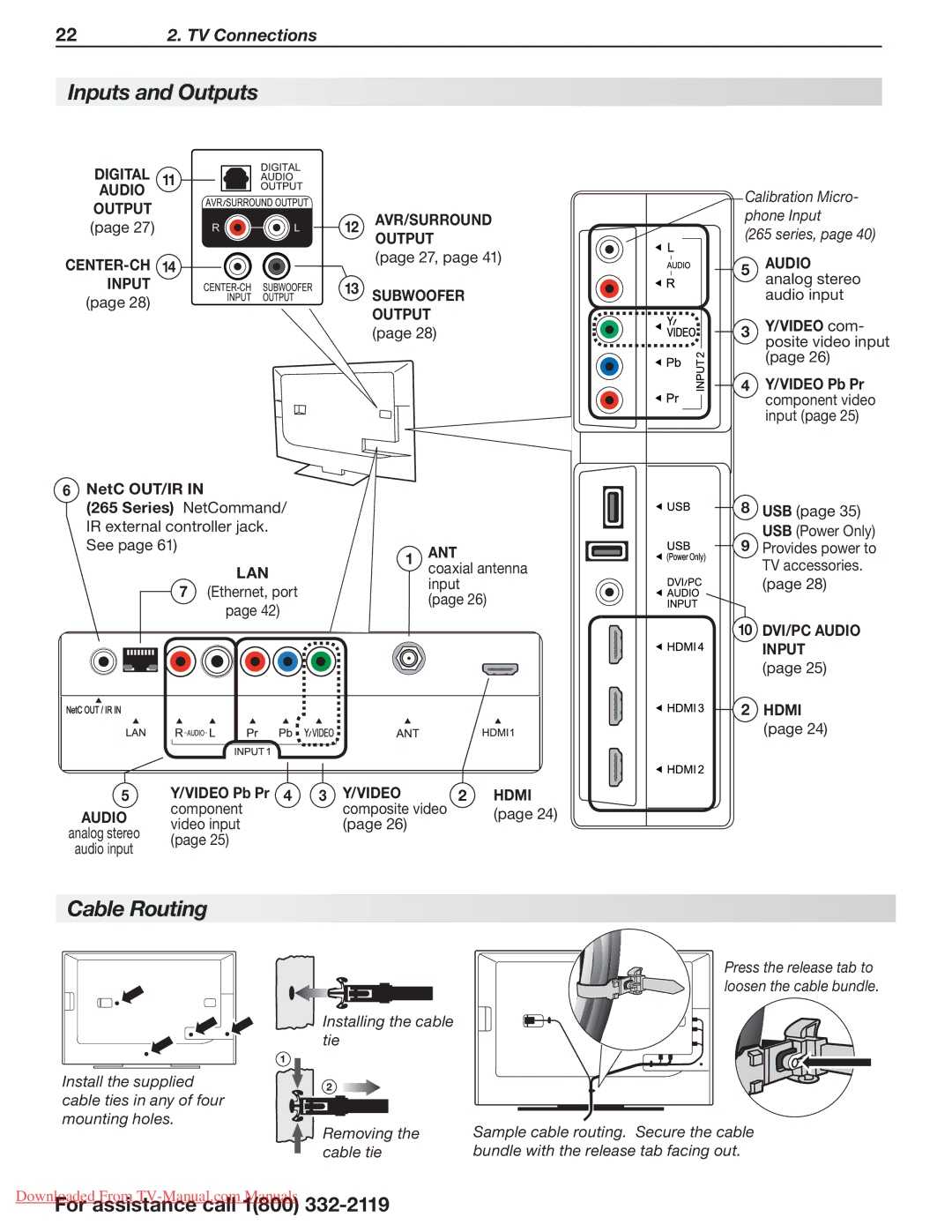
DIGITALAudio 11
OUTPUT
(page 27)
CENTER-CH 14
INPUT (page 28)
12AVR/surroundOUTPUT
(page 27, page 41)
13SUBWOOFER OUTPUT (page 28)
Calibration Micro- phone Input
(265 series, page 40)
5AUDIOanalog stereo audio input
3Y/VIDEO com- posite video input (page 26)
4Y/VIDEO Pb Pr component video input (page 25)
6NetC OUT/IR IN
(265 Series) NetCommand/ IR external controller jack. See page 61)
LAN
7 (Ethernet, port page 42)
1ANTcoaxial antenna input
(page 26)
8USB (page 35) USB (Power Only)
9Provides power to TV accessories. (page 28)
10DVI/PC AUDIO INPUT (page 25)
2HDMI (page 24)
5 | Y/VIDEO Pb Pr | 4 | 3 | Y/VIDEO | 2 HDMI |
AUDIO | component |
|
| composite video | (page 24) |
video input |
|
| (page 26) | ||
analog stereo |
|
|
| ||
(page 25) |
|
|
|
| |
audio input |
|
|
|
| |
|
|
|
|
|
Cable Routing
Install the supplied cable ties in any of four mounting holes.
Installing the cable tie
1
2
Removing the cable tie
Press the release tab to loosen the cable bundle.
Sample cable routing. Secure the cable bundle with the release tab facing out.
DownloadedFor assistanceFrom