OPERATING PROCEDURE | PHOTOS | |
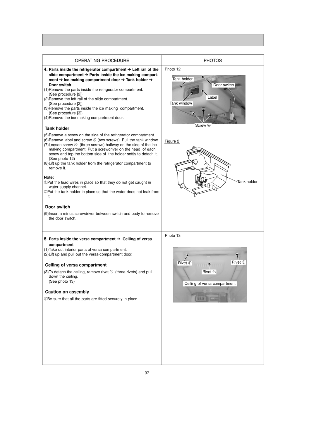
4. Parts inside the refrigerator compartment ➔ Left rail of the | Photo 12 | |
slide compartment ➔ Parts inside the ice making compart- | Tank holder | |
ment ➔ Ice making compartment door ➔ Tank holder ➔ | ||
Door switch | Door switch | |
(1)Remove the parts inside the refrigerator compartment. |
| |
(See procedure [2]) | Label | |
(2)Remove the left rail of the slide compartment. | ||
Tank window | ||
(See procedure [2]) | ||
(3)Remove the parts inside the ice making compartment. |
| |
(See procedure [3]) |
| |
(4)Remove the ice making compartment door. |
| |
Tank holder | Screw A | |
| ||
(5)Remove a screw on the side of the refrigerator compartment. |
| |
(6)Remove label and screw A (two screws). Pull the tank window. | Figure 2 | |
(7)Loosen screw A (three screws) halfway on the side of the ice | ||
| ||
making compartment. Put a screwdriver on the head of each |
| |
screw and top the bottom side of the holder softly to detach it. |
| |
(See photo 12) |
| |
(8)Lift up the tank holder from the refrigerator compartment to |
| |
remove it. |
| |
Note: | Tank holder | |
1Put the lead wires in place so that they do not get caught in | ||
water supply channel. |
| |
2Put the tank holder in place so that the water does not leak from |
| |
it. |
|
Door switch
(9)Insert a minus screwdriver between switch and body to remove the door switch.
Photo 13
5.Parts inside the versa compartment ➔ Ceiling of versa
compartment
(1)Take out interior parts of versa compartment. (2)Lift up and pull out the
Ceiling of versa compartment | Rivet F |
|
| Rivet F | ||
|
|
|
|
|
| |
|
|
|
|
|
| |
(3)To detach the ceiling, remove rivet F (three rivets) and pull |
|
| Rivet F | |||
down the ceiling. |
|
|
|
|
|
|
(See photo 13) |
|
|
|
|
|
|
| Ceiling of versa compartment |
| ||||
|
|
| ||||
|
|
|
|
|
|
|
Caution on assembly
1Be sure that all the parts are fitted securely in place.
37