OPERATING PROCEDURE
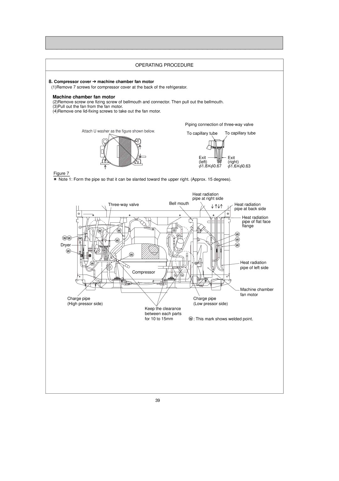
8.Compressor cover ➔ machine chamber fan motor
(1)Remove 7 screws for compressor cover at the back of the refrigerator.
Machine chamber fan motor
(2)Remove screw one fizing screw of bellmouth and connector. Then pull out the bellmouth. (3)Pull out the fan from the fan motor.
(4)Remove one
|
|
|
|
|
|
|
|
|
|
|
|
|
|
|
|
| Piping connection of | ||||||||||||
Attach U washer as the figure shown below. | To capillary tube |
|
| To capillary tube | |||||||||||||||||||||||||
|
|
|
|
|
|
|
|
|
|
|
|
|
|
|
|
|
|
| |||||||||||
|
|
|
|
|
|
|
|
|
|
|
|
|
|
|
|
|
|
|
|
|
|
|
|
|
|
|
|
|
|
|
|
|
|
|
|
|
|
|
|
|
|
|
|
|
|
|
|
|
|
|
|
|
|
|
|
|
|
|
|
|
|
|
|
|
|
|
|
|
|
|
|
|
|
|
|
|
|
|
|
|
|
|
|
|
|
|
|
|
|
|
|
|
|
|
|
|
|
|
|
|
|
|
|
|
|
|
|
|
|
|
|
|
|
|
|
|
|
|
|
Exit ![]()
![]()
![]() Exit
Exit
(left) ![]()
![]() (right)
(right)
[1.8✕[0.67 [1.6✕[0.63
Figure 7
WNote 1: Form the pipe so that it can be slanted toward the upper right. (Approx. 15 degrees).
|
|
| Heat radiation |
|
|
| pipe at right side |
| Bell mouth | Heat radiation | |
|
|
| pipe at back side |
|
|
| Heat radiation |
|
|
| pipe of flat face |
| w |
| flange |
w |
| w | |
w w |
| W | |
w |
| w | |
Dryer |
| ||
|
| w | |
w | w |
|
|
|
|
| |
w |
|
| Heat radiation |
| Compressor | pipe of left side | |
|
| ||
|
| W W |
|
|
|
| Machine chamber |
|
|
| fan motor |
Charge pipe |
|
| Charge pipe |
(High pressor side) |
|
| (Low pressor side) |
|
| Keep the clearance |
|
|
| between each parts |
|
|
| for 10 to 15mm | w : This mark shows welded point. |
39
