Projection Television OWNER’S Guide
Risk of Electric Shock Do not Open
Contents
Page
Important Safeguards
Safety Check
Power Lines
Damage Requiring Service
Replacement Parts
Following items are included with your new TV
Special Features
UnpackingYour TV
Choosing a Hookup
Shortcuts
Separate UHF and VHF antennas
Connections
TV to Antenna or Wall Outlet Cable
Connection of TV to Cable Box
Audio Video Connections
Connection of TV to VCR and Cable Box
Audio/Video Connections
Connection of TV to VCR and Antenna or Wall Outlet Cable
Antenna/Cable Connections
Connection of TV to the Active A/V Network
Connection of TV to Stereo Audio System
Connection of TV to AV Receiver
Connection of TV to DVD with Component Video Outputs
Connection of TV and Cable to Mitsubishis HD-1080 Receiver
Connectors for TV and Cable to Hdtv Receiver
Connection of TV and Cable to Hdtv Receiver
Back panel. The sequence for
Connecting the cables is Hdtv Receiver TV Back
Connect the RGB cables to
Hdtv receiver and the televesion
Input
Remote Control Functions
Menu Guide
Remote Control Functions
For best results
Operating Your Remote Control
Installing the batteries
Using the remote control with your TV
VCR codes
Remote Control of Other Audio and Video Products
Cable Box codes
Satellite Receiver codes
AV Receiver codes
Remote Control of Other Audio and Video Product
DVD Player codes
For non-DTV channels
Remote Control Channel Selection
Canceling the Sleep Timer
Remote Control of the Sleep Timer
Setting the Sleep Timer
To exit the on-screen menus
Cancel to clear a setting, or stop an automatic function
Menu System
Making Selections
Menu button
Main Menu Setup Menu
Menu Screens
Main Menu
Captions Menu Channel Edit Menu
Video Settings Menu
Advanced Features Menu
Memorize Menu
Setup Menu
After channels are memorized, your remote control will
Clock Setting Time Zone Daylight Savings
Setup Menu
Set Day
Clock Time
AV Connection Menu
AV Network
TV Speakers
AV Receiver
Other or None
Other
AV Receiver choices None
Mits-A
Mits-B
INPUT-1, INPUT-2 or
Input menu
Ant-A, Ant-B
Captions Menu
DTV Channel Guide
Captions Menu
To make the closed captions Easier to read, you can choose
Background
Channel
Channel Edit Menu
Antenna
’ / * and blank
Channel Edit Menu
Removing SQV channels using only the remote control
Adding SQV channels using only the remote control
Timer
Advanced Features Menu
Set Time Set Day
Advanced Features Menu
Input
Entry to Chip Parent Lock
To delete a character
Chip HOURS/LOCK by Time section
Main Menu Advanced Features Menu
Chip Example
V-Chip Parent Lock
Off General audience
Chip HOURS/LOCK by Time
Chip Start Time Stop
Lock by Time Lock Time Unlock Time
Main Menu Advanced Feature Menu Chip Parent Lock Menu
Convergence
Display for further instruc- tions
Reset Factory Defaults
Advanced Conver- gence
Video Display Video Mute
Timer Chip Parent Lock Convergence
Video Settings Menu AV Memory
Audio Video Settings Menu
AV Reset
Audio/Video Settings Menu
Black Enhancement
Using the Audio or Video button on the remote control
Descriptions of video settings
Audio/Video Settings Menu Adjusting the picture
Descriptions of audio settings
Audio/Video Settings Menu Adjusting the sound
English German French Italian Spanish Other Portuguese
DVD and Laser Disc players Not all functions for all models
Special Remote Control Functions
Cable Boxes and Satellite Receivers
AV Receivers Mitsubishi AV Receivers
Activating PIP/POP
Using PIP and POP Features
Using the Adjust button with PIP or POP
Using PIP and POP Features
Using the PIP Input button
Using the PIP CH button
Press to remove the black bars
Using the Exch button with PIP
Standard shape models VS-50805 and VS-60805
Formats
Anamorphic Pictures
Standard format Press Format for Expand format
Format examples
Anamorphic widescreen
Standard format
Before you begin, be sure you have
Remote Control of the Active AV Network
Infrared Emitter from page 13. Connect as shown
Special setups A/V equipment
Operating the system
Special setups TV
Emitter
Menu selection for AV connections pages TV Speakers Off
VS-50805, WS-55805 and VS-60805
Front Control Panel Functions
Front Control Panel Functions
VS-50805 and VS-60805
Back Panel Functions
Antenna ANT-A, LOOP-OUT
Back Panel Functions
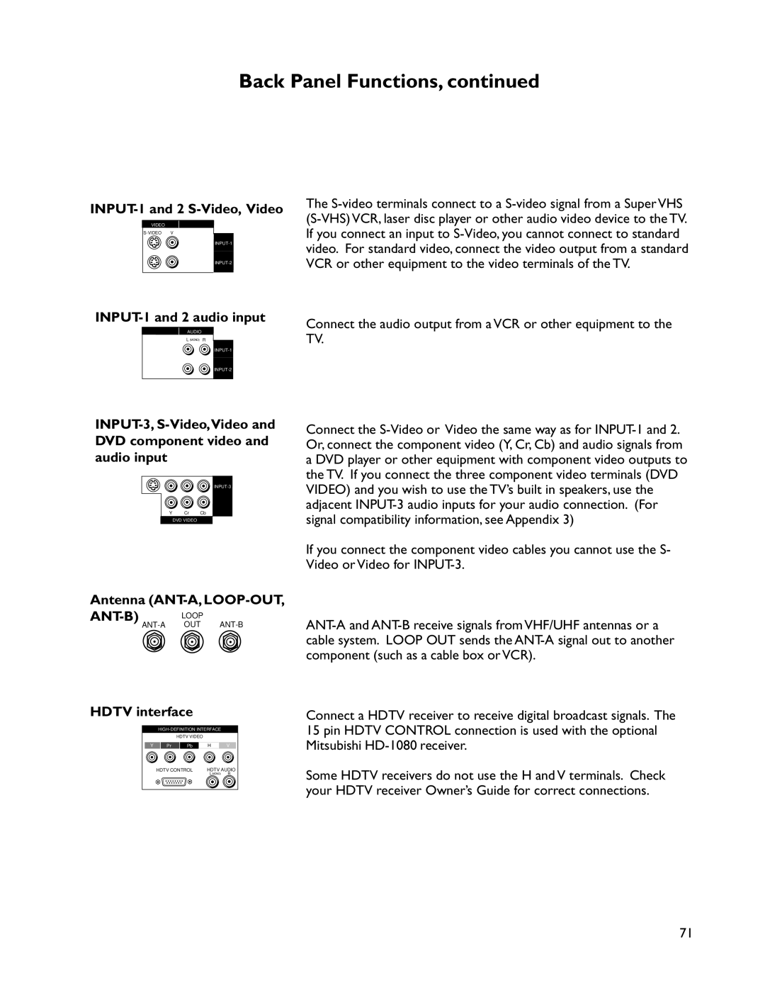
INPUT-1 and 2 S-Video, Video
INPUT-1 and 2 audio input
PIP Audio Output
Active A/V Network
Problem Possible Solution
Troubleshooting
Important Notes
Cleaning
E2RESET
If Service is Required
Removal of the Diamond Shield
Installation of the Diamond Shield
Appendix 1- Diamond ShieldTM
Appendix 1- Diamond ShieldTM
See pages 19-20 for instructions on applying these codes
Appendix 2 Remote Control Programming Codes
DBX
Appendix 2 Remote Control Programming Codes
Use the or to select V-Chip Parent Lock and press
To change or permanently cancel the V-Chip Parent Lock
Appendix 3 Bypassing the V-Chip Parent Lock
This page is blank
= 1.0V p-p includes sync 75 ohms
INPUT-3 Component Video connection compatibility
Input levels and timing with component video
This page is blank
Index
Page
Mitsubishi Digital Electronics AMERICA, INC
Jeronimo Road Irvine, CA