MODELS:
Locking Screws (continued)
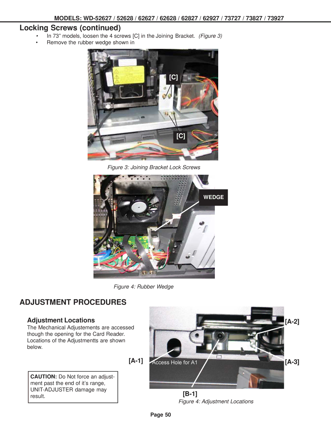
•In 73” models, loosen the 4 screws [C] in the Joining Bracket. (Figure 3)
•Remove the rubber wedge shown in
[C]
[C]
Figure 3: Joining Bracket Lock Screws
WEDGE
Figure 4: Rubber Wedge
ADJUSTMENT PROCEDURES
Adjustment Locations
The Mechanical Adjustements are accessed though the opening for the Card Reader. Locations of the Adjustmentts are shown below.
CAUTION: Do Not force an adjust- ment past the end of it’s range,
Figure 4: Adjustment Locations
Page 50
