MODELS:
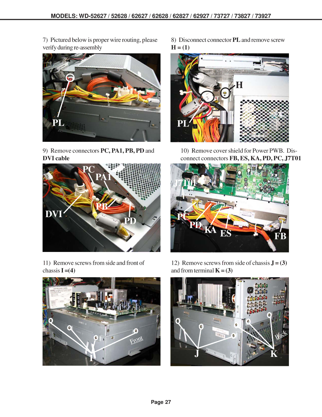
7) Pictured below is proper wire routing, please | 8) Disconnect connector PL and remove screw |
verify during | H = (1) |
PL
9)Remove connectors PC, PA1, PB, PD and
DVI cable
PCPA1
PB
![]() H
H
PL![]()
10)Remove cover shield for Power PWB. Dis- connect connectors FB, ES, KA, PD, PC, J7T01
J7T01
DVI
PD
PCPD KA ES | FB |
11)Remove screws from side and front of chassis I =(4)
12)Remove screws from side of chassis J = (3) and from terminal K = (3)
Front

 Back
Back
IJK
Page 27
