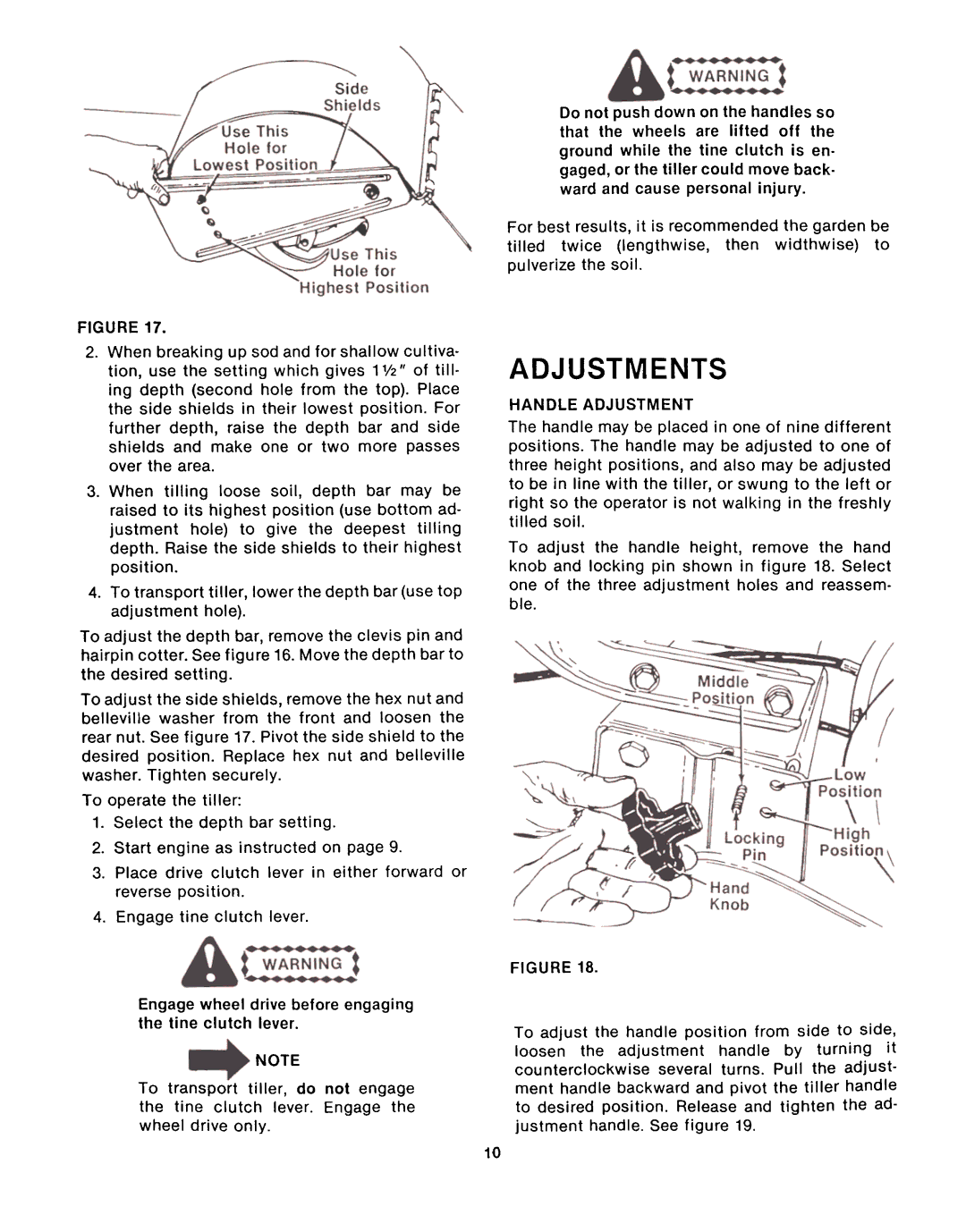
FIGURE 17.
2.When breaking up sod and for shallow cultiva- tion, use the setting which gives 1V2" of till- ing depth (second hole from the top). Place the side shields in their lowest position. For further depth, raise the depth bar and side shields and make one or two more passes over the area.
3.When tilling loose soil, depth bar may be raised to its highest position (use bottom ad- justment hole) to give the deepest tilling depth. Raise the side shields to their highest position.
4.To transport tiller, lower the depth bar (use top
adjustment hole).
To adjust the depth bar, remove the clevis pin and hairpin cotter. See figure 16. Move the depth bar to the desired setting.
To adjust the side shields, remove the hex nut and belleville washer from the front and loosen the rear nut. See figure 17. Pivot the side shield to the desired position. Replace hex nut and belleville washer. Tighten securely.
To operate the tiller:
1.Select the depth bar setting.
2.Start engine as instructed on page 9.
3.Place drive clutch lever in either forward or reverse position.
4.Engage tine clutch lever.
Engage wheel drive before engaging the tine clutch lever.
NOTE
To transport tiller, do not engage the tine clutch lever. Engage the wheel drive only.
Do not push down on the handles so that the wheels are lifted off the ground while the tine clutch is en- gaged, or the tiller could move back- ward and cause personal injury.
For best results, it is recommended the garden be
tilled twice (lengthwise, then widthwise) to pulverize the soil.
ADJUSTMENTS
HANDLE ADJUSTMENT
The handle may be placed in one of nine different positions. The handle may be adjusted to one of three height positions, and also may be adjusted to be in line with the tiller, or swung to the left or right so the operator is not walking in the freshly
tilled soil.
To adjust the handle height, remove the hand knob and locking pin shown in figure 18. Select one of the three adjustment holes and reassem.
ble.
FIGURE 18.
To adjust the handle position from side to side,
loosen the adjustment handle by turning it
counterclockwise several turns. Pull the adjust- ment handle backward and pivot the tiller handle to desired position. Release and tighten the ad-
justment handle. See figure 19.
10