| |
| ., |
|
|
I ~ @ @ @ T- e
L
,
Q-~@@@
FIGURE 1.
![]() AE
AE
FIGURE 2.
ASSEMBLY
NOTE
This unit is shipped WITHOUT GAS- OLINE or OIL. After assembly, see separate engine manual for proper fuel and engine oil
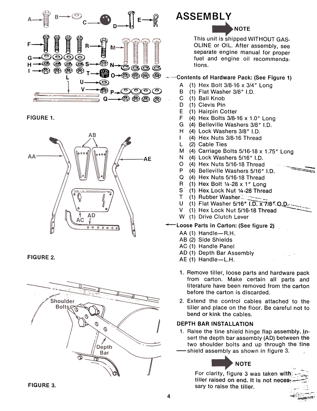
~Contents |
| of | Hardware | Pack: | (See | Figure | 1) |
| ||||
A | (1) | Hex | Bolt | x | 3/4" | Long |
|
| ||||
B | (1) | Flat | Washer | 3/8" |
| I.D. |
|
|
|
| ||
C | (1) | Ball | Knob |
|
|
|
|
|
|
|
| |
D | (1) | Clevis |
| Pin |
|
|
|
|
|
|
|
|
E | (1) | Hairpin |
| Cotter |
|
|
|
|
|
|
| |
F | (4) | Hex | Bolts |
| x 1.0" |
| Long |
|
| |||
G | (4) | Belleville |
| Washers |
|
| 3/8" |
| I.D. |
|
| |
H | (4) | Lock |
| Washers | 3/8" |
| I.D. |
|
|
|
| |
I | (4) | Hex | Nuts | Thread |
|
|
|
| ||||
L | (2) | Cable |
| Ties |
|
|
|
|
|
|
|
|
M | (4) | Carriage | Bolts |
| x | 1.75" | Long |
| ||||
N | (4) | Lock |
| Washers | 5/16" | I.D. |
|
|
| |||
0 | (4) | Hex | Nuts |
| Thread |
|
| - | ||||
P | (4) | Belleville |
| Washers |
|
| 5/16" | I.D. |
| |||
Q | (4) | Hex | Nuts |
| Thread |
|
|
|
| |||
R | (1) | Hex | Bolt | 1/4 | x | 1" | Long |
|
|
| ||
S | (1) | He~Lqck |
| Nut | Thread |
|
| |||||
T | (1) | Rubber |
| Washer,~~_- |
|
|
|
|
|
| ||
UV | (1) | HexFlat | WasherLock | Nut | ||||||||
W | (1) | Drive |
| Clutch |
|
|
|
| ||||
|
| Parts | in | Carton: | (See | figure | 2) |
|
| |||
AA (1) |
|
|
|
|
|
|
|
| ||||
AB | (2) | Side | Shields |
|
|
|
|
|
|
|
| |
AC | (1) | Handle |
| Panel |
|
|
|
|
|
|
| |
AD | (1) | Depth |
| Bar | Assembly |
|
|
|
|
|
| |
AE | (1) |
|
|
|
|
|
|
|
| |||
FIGURE 3.
4
1.Remove tiller, loose parts and hardware pack from carton. Make certain all parts and literature have been removed from the carton before the carton is discarded.
2.Extend the control cables attached to the ti!ler and place on the floor. Be careful not to bend or kink the cables.
DEPTH BAR INSTAllATION
1.Raise the tine shield hinge flap assembly. )p- sert the depth bar assembly (AD) between the two shoulder bolts and up through the
assembly as shown in figure 3.
NOTE
."
For clarity, figure 3 was taken with.,
sary to raise the tiller. | .: |