Serial Cables |
|
|
|
| |
XT TYPE. | CPU | CONTROLLER | |||
PIN 1 | Frame Ground | > Shell | (solder) | ||
PIN 2 | TX Transmit | > PIN 3 RX Receive | |||
PIN 3 | RX Receive | ||||
PIN 5 | CTS Clear | PIN 8 DSR Ready | |||
PIN 7 | Signal Ground | > PIN 5 Signal & Frame | |||
|
|
|
| ||
AT TYPE. | CPU | CONTROLLER | |||
| Note : | ||||
PIN 3 | TX Transmit | > PIN 3 RX Receive | |||
PIN 2 | RX Receive | PIN 2 TX Transmit | |||
PIN 8 | CTS Clear | PIN 8 DSR Ready | |||
PIN 5 | Signal Ground | > PIN 5 Signal & Frame | |||
PIN 4 | DTR Ready | > PIN 4 DTR Ready | |||
Shell | Frame Ground | > Shell Signal & Frame | |||
|
|
|
| pin to pin cable |
|
MAC DIN. | CPU | CONTROLLER | |||
PIN 5 | RX | In- | PIN 2 TX Transmit | ||
PIN 3 | TX | Out- | RX Receive | ||
PIN 2 | CTS Hand In | PIN 8 DSR Ready | |||
PIN 4 | Signal Ground | > PIN 5 Signal & Frame | |||
PIN 8 | RX | In+ | ' |
| |
PIN 1 | DTR | > PIN 4 DTR | |||
Shell | Frame Ground | > Shell Signal & Frame | |||
|
|
| MAC to IBM Adaptor Cable | ||
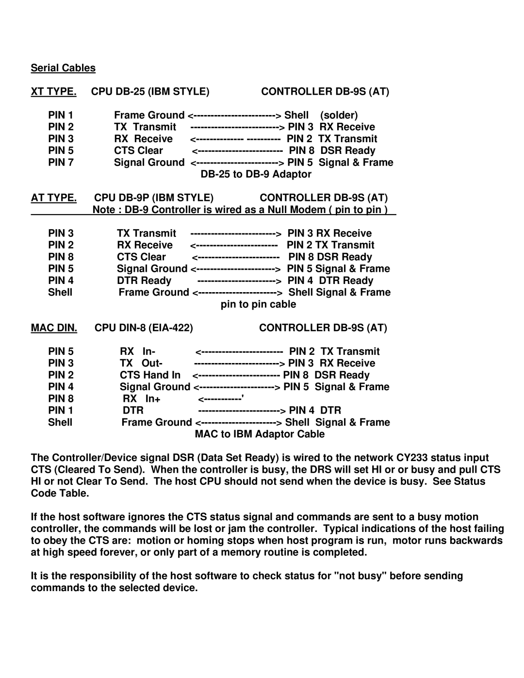
The Controller/Device signal DSR (Data Set Ready) is wired to the network CY233 status input CTS (Cleared To Send). When the controller is busy, the DRS will set HI or or busy and pull CTS HI or not Clear To Send. The host CPU should not send when the device is busy. See Status Code Table.
If the host software ignores the CTS status signal and commands are sent to a busy motion controller, the commands will be lost or jam the controller. Typical indications of the host failing to obey the CTS are: motion or homing stops when host program is run, motor runs backwards at high speed forever, or only part of a memory routine is completed.
It is the responsibility of the host software to check status for "not busy" before sending commands to the selected device.
