Memory Selection Jumpers JP3 – JP10
The factory setting for the jumpers should be correct for the memory devices that came with your board. If you add or modify the type or size of memory, you must change the following jumpers accordingly. All jumpers are
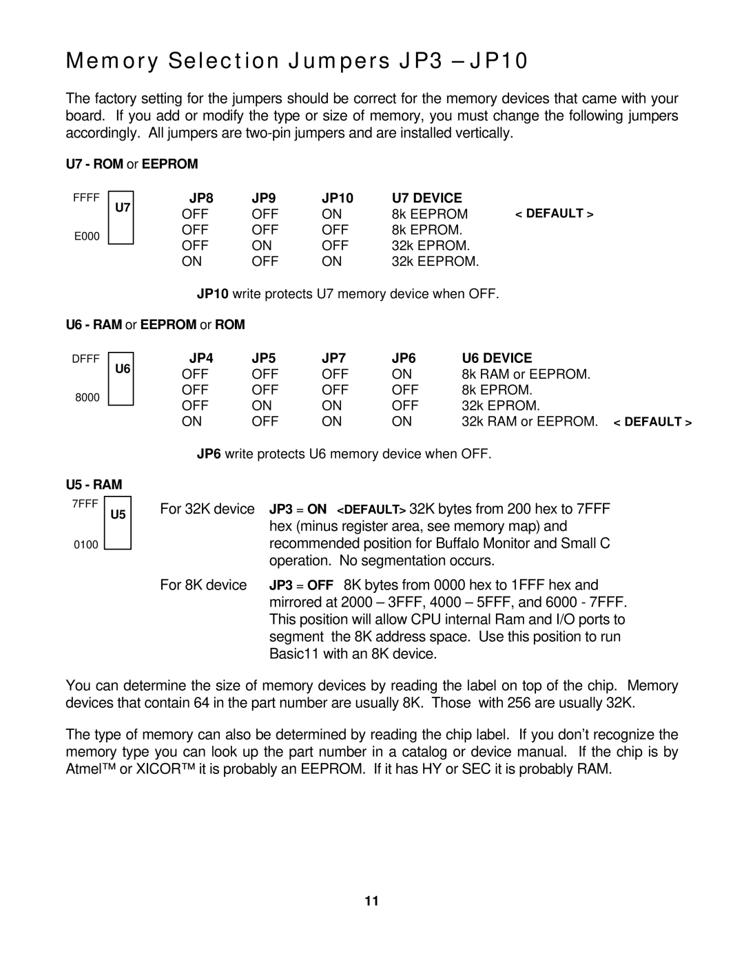
U7 - ROM or EEPROM
FFFF
E000
U7
JP8 | JP9 | JP10 | U7 DEVICE |
|
OFF | OFF | ON | 8k EEPROM | < DEFAULT > |
OFF | OFF | OFF | 8k EPROM. |
|
OFF | ON | OFF | 32k EPROM. |
|
ON | OFF | ON | 32k EEPROM. |
|
JP10 write protects U7 memory device when OFF.
U6 - RAM or EEPROM or ROM
DFFF
U6
8000
U5 - RAM
7FFF
U5
0100
JP4 | JP5 | JP7 | JP6 | U6 DEVICE |
OFF | OFF | OFF | ON | 8k RAM or EEPROM. |
OFF | OFF | OFF | OFF | 8k EPROM. |
OFF | ON | ON | OFF | 32k EPROM. |
ON | OFF | ON | ON | 32k RAM or EEPROM. < DEFAULT > |
JP6 write protects U6 memory device when OFF. | ||||
For 32K device | JP3 = ON <DEFAULT> 32K bytes from 200 hex to 7FFF |
| hex (minus register area, see memory map) and |
| recommended position for Buffalo Monitor and Small C |
| operation. No segmentation occurs. |
For 8K device | JP3 = OFF 8K bytes from 0000 hex to 1FFF hex and |
| mirrored at 2000 – 3FFF, 4000 – 5FFF, and 6000 - 7FFF. |
| This position will allow CPU internal Ram and I/O ports to |
| segment the 8K address space. Use this position to run |
| Basic11 with an 8K device. |
You can determine the size of memory devices by reading the label on top of the chip. Memory devices that contain 64 in the part number are usually 8K. Those with 256 are usually 32K.
The type of memory can also be determined by reading the chip label. If you don’t recognize the memory type you can look up the part number in a catalog or device manual. If the chip is by Atmel™ or XICOR™ it is probably an EEPROM. If it has HY or SEC it is probably RAM.
11