AUX_PORT
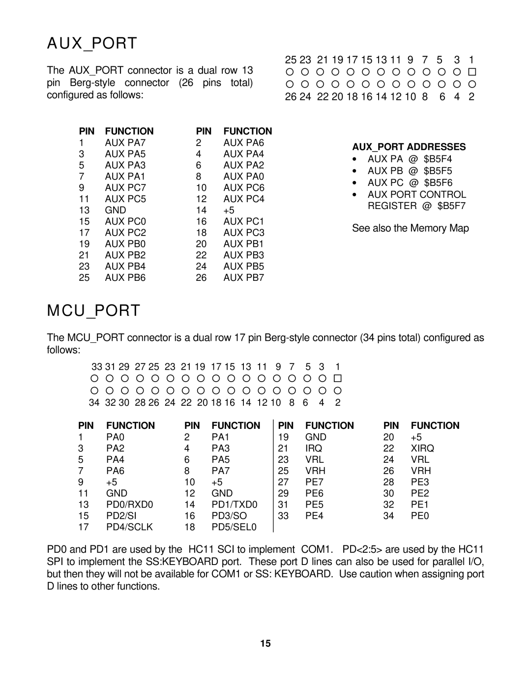
The AUX_PORT connector is a dual row 13 pin
25 23 | 21 19 17 15 13 11 | 9 | 7 | 5 | 3 | 1 |
¡¡ ¡ ¡ ¡ ¡ ¡ ¡ ¡ ¡ ¡ ¡ ¨
¡¡ ¡ ¡ ¡ ¡ ¡ ¡ ¡ ¡ ¡ ¡ ¡
26 24 | 22 20 18 16 14 12 10 | 8 | 6 | 4 | 2 |
PIN | FUNCTION | PIN | FUNCTION |
1 | AUX PA7 | 2 | AUX PA6 |
3 | AUX PA5 | 4 | AUX PA4 |
5 | AUX PA3 | 6 | AUX PA2 |
7 | AUX PA1 | 8 | AUX PA0 |
9 | AUX PC7 | 10 | AUX PC6 |
11 | AUX PC5 | 12 | AUX PC4 |
13 | GND | 14 | +5 |
15 | AUX PC0 | 16 | AUX PC1 |
17 | AUX PC2 | 18 | AUX PC3 |
19 | AUX PB0 | 20 | AUX PB1 |
21 | AUX PB2 | 22 | AUX PB3 |
23 | AUX PB4 | 24 | AUX PB5 |
25 | AUX PB6 | 26 | AUX PB7 |
AUX_PORT ADDRESSES
∙AUX PA @ $B5F4
∙AUX PB @ $B5F5
∙AUX PC @ $B5F6
∙AUX PORT CONTROL REGISTER @ $B5F7
See also the Memory Map
MCU_PORT
The MCU_PORT connector is a dual row 17 pin
33 31 29 | 27 25 | 23 | 21 19 | 17 15 | 13 | 11 | 9 | 7 | 5 | 3 | 1 |
¡¡ ¡ ¡ ¡ ¡ ¡ ¡ ¡ ¡ ¡ ¡ ¡ ¡ ¡ ¡ ¨
¡¡ ¡ ¡ ¡ ¡ ¡ ¡ ¡ ¡ ¡ ¡ ¡ ¡ ¡ ¡ ¡
34 | 32 30 | 28 26 | 24 | 22 | 20 18 16 | 14 | 12 10 | 8 | 6 | 4 | 2 |
PIN | FUNCTION | PIN | FUNCTION |
1 | PA0 | 2 | PA1 |
3 | PA2 | 4 | PA3 |
5 | PA4 | 6 | PA5 |
7 | PA6 | 8 | PA7 |
9 | +5 | 10 | +5 |
11 | GND | 12 | GND |
13 | PD0/RXD0 | 14 | PD1/TXD0 |
15 | PD2/SI | 16 | PD3/SO |
17 | PD4/SCLK | 18 | PD5/SEL0 |
PIN | FUNCTION | PIN | FUNCTION |
19 | GND | 20 | +5 |
21 | IRQ | 22 | XIRQ |
23 | VRL | 24 | VRL |
25 | VRH | 26 | VRH |
27 | PE7 | 28 | PE3 |
29 | PE6 | 30 | PE2 |
31 | PE5 | 32 | PE1 |
33 | PE4 | 34 | PE0 |
PD0 and PD1 are used by the HC11 SCI to implement COM1. PD<2:5> are used by the HC11 SPI to implement the SS:KEYBOARD port. These port D lines can also be used for parallel I/O, but then they will not be available for COM1 or SS: KEYBOARD. Use caution when assigning port D lines to other functions.
15
