PORTS AND CONNECTORS
LCD_PORT
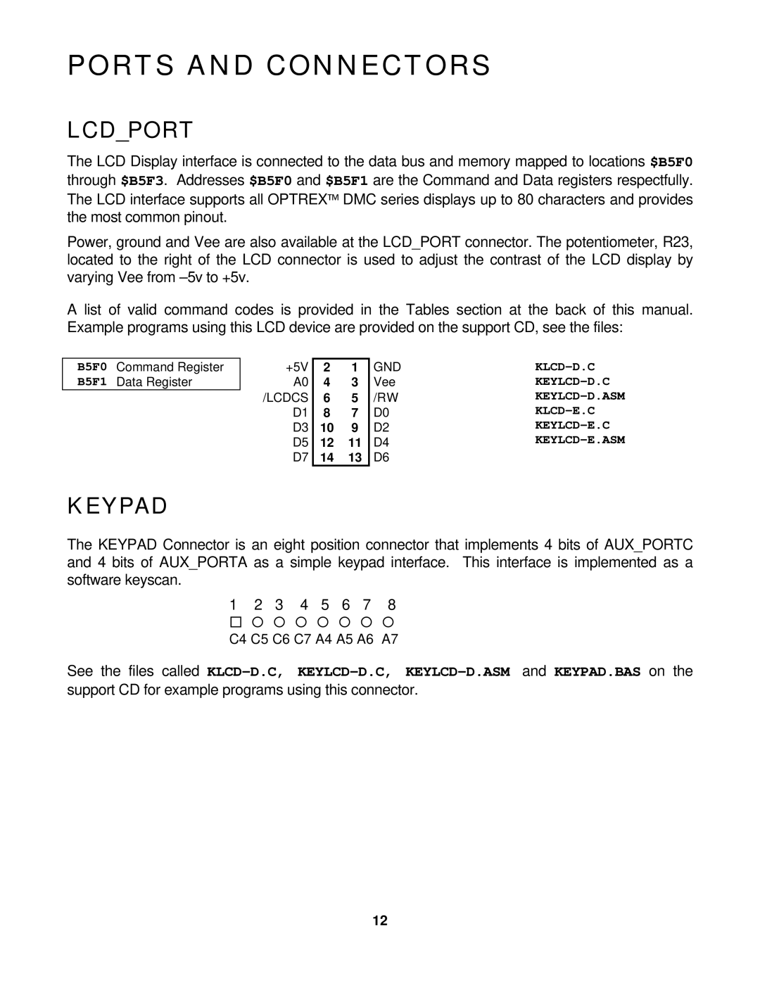
The LCD Display interface is connected to the data bus and memory mapped to locations $B5F0 through $B5F3. Addresses $B5F0 and $B5F1 are the Command and Data registers respectfully. The LCD interface supports all OPTREX™ DMC series displays up to 80 characters and provides the most common pinout.
Power, ground and Vee are also available at the LCD_PORT connector. The potentiometer, R23, located to the right of the LCD connector is used to adjust the contrast of the LCD display by varying Vee from
A list of valid command codes is provided in the Tables section at the back of this manual. Example programs using this LCD device are provided on the support CD, see the files:
B5F0 Command Register B5F1 Data Register
+5V | 2 | 1 | GND | |
A0 | 4 | 3 | Vee | |
/LCDCS | 6 | 5 | /RW | |
D1 | 8 | 7 | D0 | |
D3 | 10 | 9 | D2 | |
D5 | 12 | 11 | D4 | |
D7 | 14 | 13 | D6 |
|
KEYPAD
The KEYPAD Connector is an eight position connector that implements 4 bits of AUX_PORTC and 4 bits of AUX_PORTA as a simple keypad interface. This interface is implemented as a software keyscan.
1 2 3 4 5 6 7 8
¨¡ ¡ ¡ ¡ ¡ ¡ ¡
C4 C5 C6 C7 A4 A5 A6 A7
See the files called
12