SERIAL PORTS
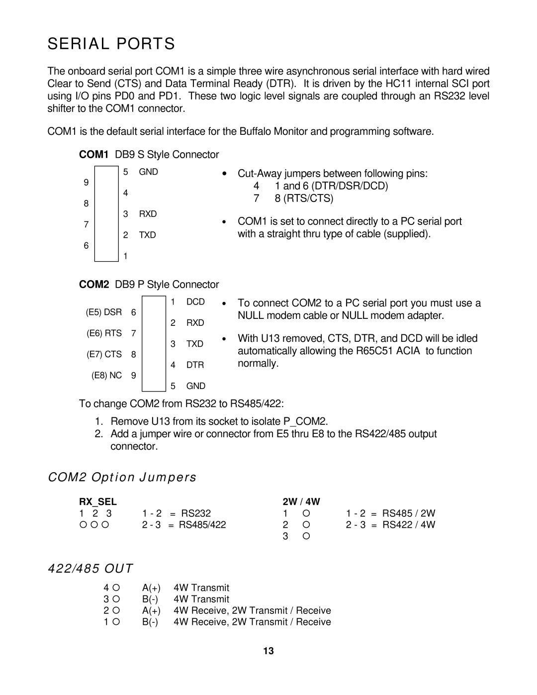
The onboard serial port COM1 is a simple three wire asynchronous serial interface with hard wired Clear to Send (CTS) and Data Terminal Ready (DTR). It is driven by the HC11 internal SCI port using I/O pins PD0 and PD1. These two logic level signals are coupled through an RS232 level shifter to the COM1 connector.
COM1 is the default serial interface for the Buffalo Monitor and programming software.
COM1 DB9 S Style Connector
Ÿ 5 GND
9Ÿ
Ÿ4
8Ÿ
Ÿ 3 RXD
7Ÿ
Ÿ 2 TXD
6Ÿ
Ÿ1
∙
7 à 8 (RTS/CTS)
∙COM1 is set to connect directly to a PC serial port with a straight thru type of cable (supplied).
COM2 DB9 P Style Connector
(E5) DSR 6
(E6) RTS 7
(E7) CTS 8
(E8) NC 9
Ÿ 1 DCD
Ÿ
Ÿ 2 RXD
Ÿ
Ÿ 3 TXD
Ÿ
Ÿ 4 DTR
Ÿ
Ÿ 5 GND
∙To connect COM2 to a PC serial port you must use a NULL modem cable or NULL modem adapter.
∙With U13 removed, CTS, DTR, and DCD will be idled automatically allowing the R65C51 ACIA to function normally.
To change COM2 from RS232 to RS485/422:
1.Remove U13 from its socket to isolate P_COM2.
2.Add a jumper wire or connector from E5 thru E8 to the RS422/485 output connector.
COM2 Option Jumpers
RX_SEL |
| 2W / 4W |
|
|
| |
1 2 3 | 1 - 2 = RS232 | 1 | ¡ | 1 - 2 | = | RS485 / 2W |
¡ ¡ ¡ | 2 - 3 = RS485/422 | 2 | ¡ | 2 - 3 | = | RS422 / 4W |
|
| 3 | ¡ |
|
|
|
422/485 OUT
4 ¡ | A(+) | 4W | Transmit |
3 ¡ | 4W | Transmit | |
2 ¡ | A(+) | 4W | Receive, 2W Transmit / Receive |
1 ¡ | 4W | Receive, 2W Transmit / Receive |
13
