MEMORY MAP
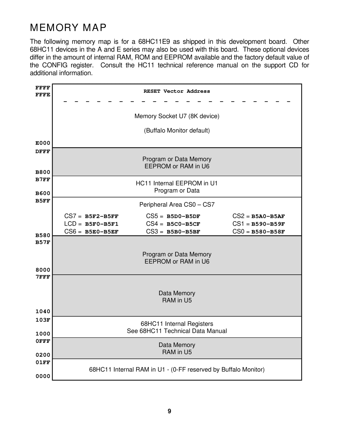
The following memory map is for a 68HC11E9 as shipped in this development board. Other 68HC11 devices in the A and E series may also be used with this board. These optional devices differ in the amount of internal RAM, ROM and EEPROM available and the factory default value of the CONFIG register. Consult the HC11 technical reference manual on the support CD for additional information.
FFFF FFFE
E000 DFFF
B800
B7FF
B600
B5FF
B580
B57F
8000
7FFF
1040
103F
1000
0FFF
0200
01FF
0000
RESET Vector Address
- - - - - - - - - - - - - - - - - - - - -
Memory Socket U7 (8K device)
(Buffalo Monitor default)
Program or Data Memory
EEPROM or RAM in U6
HC11 Internal EEPROM in U1
Program or Data
|
| Peripheral Area CS0 – CS7 |
|
|
| CS7 = | CS5 = | CS2 = |
|
| LCD = | CS4 = | CS1 = |
|
| CS6 = | CS3 = | CS0 = |
|
|
| Program or Data Memory |
|
|
|
| EEPROM or RAM in U6 |
|
|
|
|
|
|
|
|
| Data Memory |
|
|
|
| RAM in U5 |
|
|
|
|
|
|
|
|
| 68HC11 Internal Registers |
|
|
|
| See 68HC11 Technical Data Manual |
|
|
|
|
|
|
|
|
| Data Memory |
|
|
|
| RAM in U5 |
|
|
|
|
|
|
|
68HC11 Internal RAM in U1 -
9