BUS_PORT
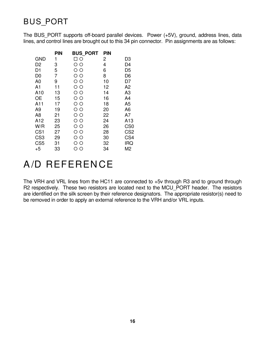
The BUS_PORT supports
| PIN | BUS_PORT | PIN |
|
GND | 1 | ¨ ¡ | 2 | D3 |
D2 | 3 | ¡ ¡ | 4 | D4 |
D1 | 5 | ¡ ¡ | 6 | D5 |
D0 | 7 | ¡ ¡ | 8 | D6 |
A0 | 9 | ¡ ¡ | 10 | D7 |
A1 | 11 | ¡ ¡ | 12 | A2 |
A10 | 13 | ¡ ¡ | 14 | A3 |
OE | 15 | ¡ ¡ | 16 | A4 |
A11 | 17 | ¡ ¡ | 18 | A5 |
A9 | 19 | ¡ ¡ | 20 | A6 |
A8 | 21 | ¡ ¡ | 22 | A7 |
A12 | 23 | ¡ ¡ | 24 | A13 |
W/R | 25 | ¡ ¡ | 26 | CS0 |
CS1 | 27 | ¡ ¡ | 28 | CS2 |
CS3 | 29 | ¡ ¡ | 30 | CS4 |
CS5 | 31 | ¡ ¡ | 32 | IRQ |
+5 | 33 | ¡ ¡ | 34 | M2 |
A/D REFERENCE
The VRH and VRL lines from the HC11 are connected to +5v through R3 and to ground through R2 respectively. These two resistors are located next to the MCU_PORT header. The resistors are identified on the silk screen by their reference designators. The appropriate resistor(s) need to be removed in order to apply an external reference to the VRH and/or VRL inputs.
16