Hardware Installation |
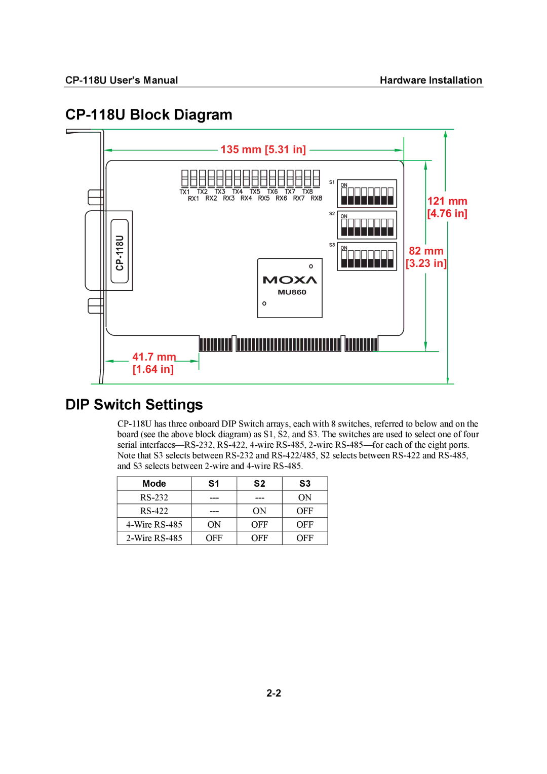
CP-118U Block Diagram
135 mm [5.31 in]
MU860
41.7mm [1.64 in]
121mm [4.76 in]
82mm [3.23 in]
DIP Switch Settings
Note that S3 selects between
Mode | S1 | S2 | S3 |
ON | |||
ON | OFF | ||
ON | OFF | OFF | |
OFF | OFF | OFF |
Hardware Installation |
135 mm [5.31 in]
MU860
41.7mm [1.64 in]
121mm [4.76 in]
82mm [3.23 in]
Note that S3 selects between
Mode | S1 | S2 | S3 |
ON | |||
ON | OFF | ||
ON | OFF | OFF | |
OFF | OFF | OFF |