These units are certified for residential applications. For installation in a residential garage, these units must be installed so that burners and ignition source are located no less than 18” (457mm) above floor. Heater must be located or protected to avoid physical damage by vehicles. Refer to CSA B149.1, Natural Gas and Propane Installation Code current edition.
In a confined area, the heater must be installed in accordance with the CSA B149.1, Natural Gas and Propane Installation Code. Be sure to check with local codes and ordinances for additional requirements.
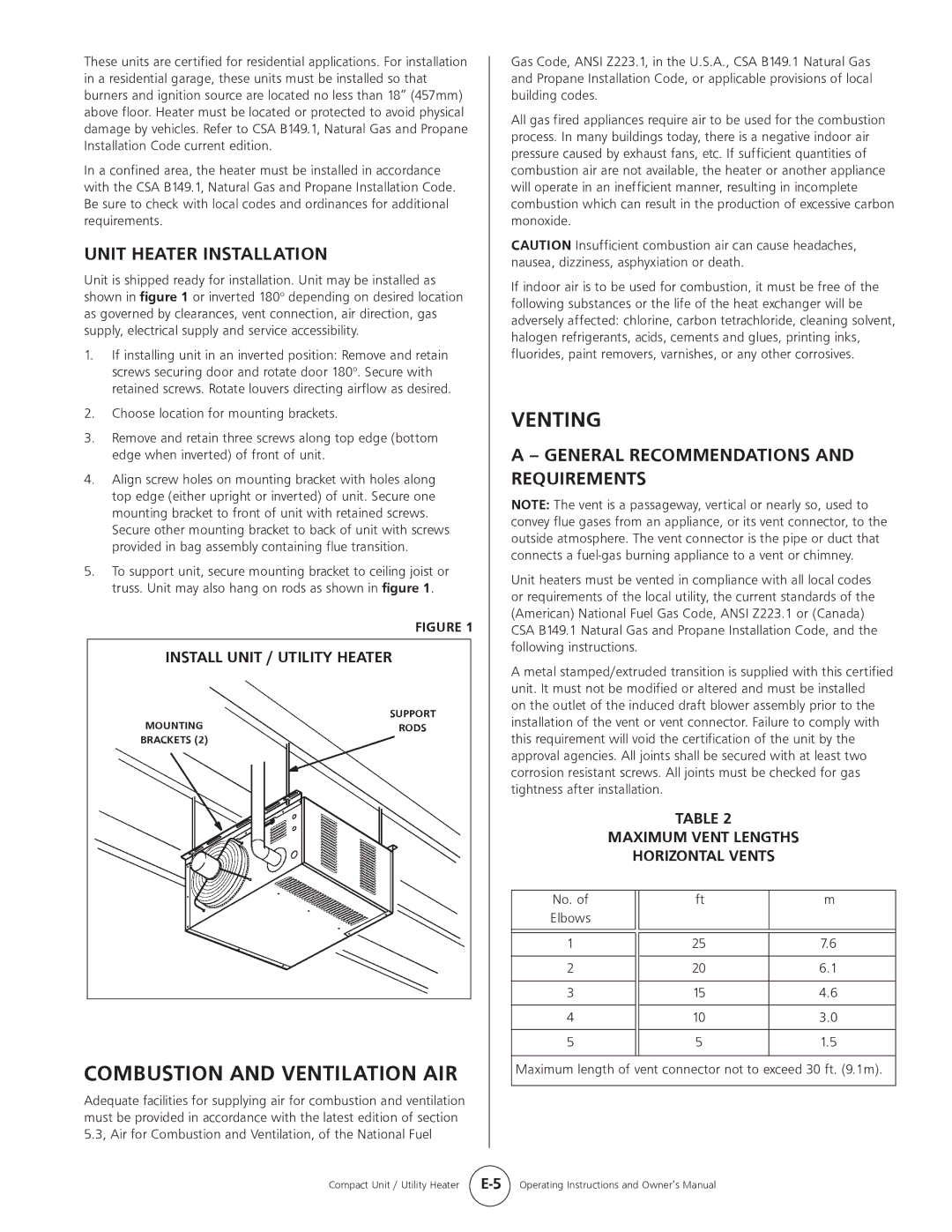
UNIT HEATER INSTALLATION
Unit is shipped ready for installation. Unit may be installed as shown in figure 1 or inverted 180o depending on desired location as governed by clearances, vent connection, air direction, gas supply, electrical supply and service accessibility.
1.If installing unit in an inverted position: Remove and retain screws securing door and rotate door 180o. Secure with retained screws. Rotate louvers directing airflow as desired.
2.Choose location for mounting brackets.
3.Remove and retain three screws along top edge (bottom edge when inverted) of front of unit.
4.Align screw holes on mounting bracket with holes along top edge (either upright or inverted) of unit. Secure one mounting bracket to front of unit with retained screws.
Secure other mounting bracket to back of unit with screws provided in bag assembly containing flue transition.
5.To support unit, secure mounting bracket to ceiling joist or truss. Unit may also hang on rods as shown in figure 1.
FIGURE 1
INSTALL UNIT / UTILITY HEATER
SUPPORT
MOUNTINGRODS BRACKETS (2)
COMBUSTION AND VENTILATION AIR
Adequate facilities for supplying air for combustion and ventilation must be provided in accordance with the latest edition of section 5.3, Air for Combustion and Ventilation, of the National Fuel
Gas Code, ANSI Z223.1, in the U.S.A., CSA B149.1 Natural Gas and Propane Installation Code, or applicable provisions of local building codes.
All gas fired appliances require air to be used for the combustion process. In many buildings today, there is a negative indoor air pressure caused by exhaust fans, etc. If sufficient quantities of combustion air are not available, the heater or another appliance will operate in an inefficient manner, resulting in incomplete combustion which can result in the production of excessive carbon monoxide.
CAUTION Insufficient combustion air can cause headaches, nausea, dizziness, asphyxiation or death.
If indoor air is to be used for combustion, it must be free of the following substances or the life of the heat exchanger will be adversely affected: chlorine, carbon tetrachloride, cleaning solvent, halogen refrigerants, acids, cements and glues, printing inks, fluorides, paint removers, varnishes, or any other corrosives.
VENTING
A – GENERAL RECOMMENDATIONS AND REQUIREMENTS
NOTE: The vent is a passageway, vertical or nearly so, used to convey flue gases from an appliance, or its vent connector, to the outside atmosphere. The vent connector is the pipe or duct that connects a
Unit heaters must be vented in compliance with all local codes or requirements of the local utility, the current standards of the (American) National Fuel Gas Code, ANSI Z223.1 or (Canada)
CSA B149.1 Natural Gas and Propane Installation Code, and the following instructions.
A metal stamped/extruded transition is supplied with this certified unit. It must not be modified or altered and must be installed
on the outlet of the induced draft blower assembly prior to the installation of the vent or vent connector. Failure to comply with this requirement will void the certification of the unit by the approval agencies. All joints shall be secured with at least two corrosion resistant screws. All joints must be checked for gas tightness after installation.
TABLE 2
MAXIMUM VENT LENGTHS
HORIZONTAL VENTS
No. of | ft | m |
Elbows |
|
|
|
|
|
|
|
|
1 | 25 | 7.6 |
|
|
|
2 | 20 | 6.1 |
|
|
|
3 | 15 | 4.6 |
|
|
|
4 | 10 | 3.0 |
|
|
|
5 | 5 | 1.5 |
|
|
|
Maximum length of vent connector not to exceed 30 ft. (9.1m).
Compact Unit / Utility Heater | Operating Instructions and Owner’s Manual |