▍Hardware Setup
Power Supply
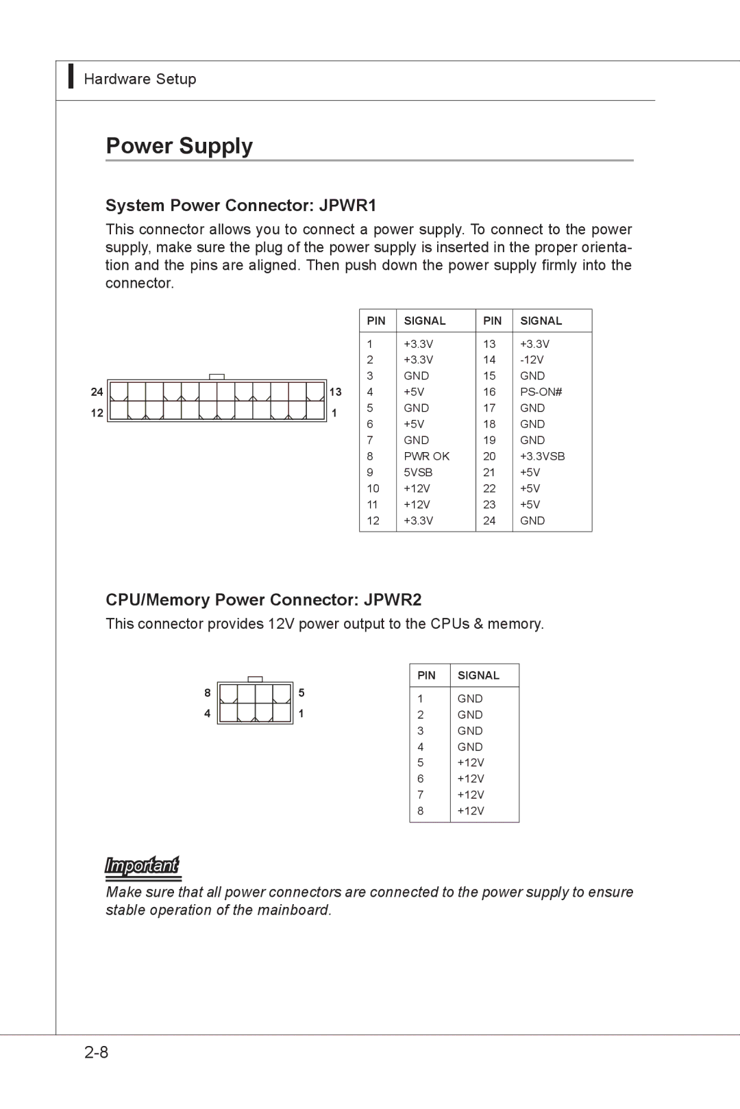
System Power Connector: JPWR1
This connector allows you to connect a power supply. To connect to the power supply, make sure the plug of the power supply is inserted in the proper orienta- tion and the pins are aligned. Then push down the power supply firmly into the connector.
24
12
| PIN | SIGNAL | PIN | SIGNAL | |
|
|
|
|
| |
| 1 | +3.3V | 13 | +3.3V | |
| 2 | +3.3V | 14 | ||
| 3 | GND | 15 | GND | |
13 | 4 | +5V | 16 | ||
1 | 5 | GND | 17 | GND | |
6 | +5V | 18 | GND | ||
| |||||
| 7 | GND | 19 | GND | |
| 8 | PWR OK | 20 | +3.3VSB | |
| 9 | 5VSB | 21 | +5V | |
| 10 | +12V | 22 | +5V | |
| 11 | +12V | 23 | +5V | |
| 12 | +3.3V | 24 | GND | |
|
|
|
|
|
CPU/Memory Power Connector: JPWR2
This connector provides 12V power output to the CPUs & memory.
8
4
Important
| PIN | SIGNAL | |
5 |
|
| |
1 | GND | ||
| |||
1 | 2 | GND | |
| 3 | GND | |
| 4 | GND | |
| 5 | +12V | |
| 6 | +12V | |
| 7 | +12V | |
| 8 | +12V | |
|
|
|
Make sure that all power connectors are connected to the power supply to ensure stable operation of the mainboard.