
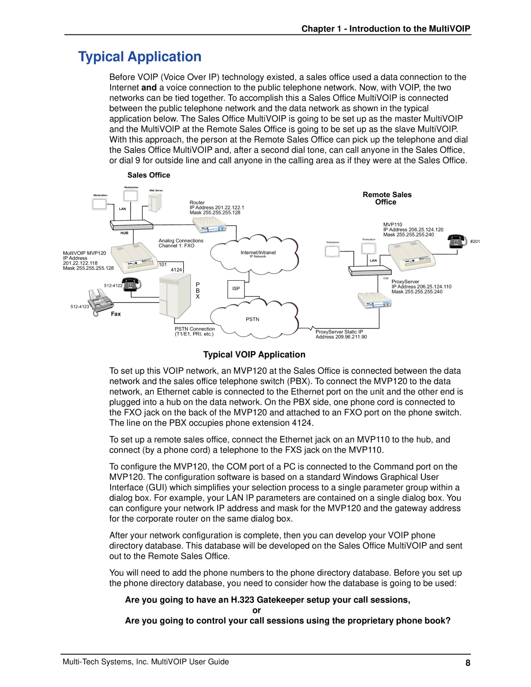
MVP120 specifications
Multi-Tech Systems MVP120 is an advanced communication device designed to enhance various applications across industries. It is a part of the Multi-Tech's MVP (MultiVoIP) product line, which is renowned for its versatility and robustness in VoIP (Voice over Internet Protocol) solutions. The MVP120 provides businesses with an efficient way to convert traditional analog voice signals into digital formats suitable for transmission over the Internet or other digital networks.One of the main features of the MVP120 is its support for up to 12 voice channels. This capability allows multiple calls to be managed simultaneously, making it an ideal choice for businesses with high call volumes. The device offers a seamless integration with existing telephony systems, enabling users to retain their current infrastructure while benefiting from the added advantages of VoIP technology.
The MVP120 utilizes advanced Voice over IP protocols, including SIP (Session Initiation Protocol), which facilitates the establishment, management, and termination of voice sessions over the internet. SIP compatibility enhances interoperability with various service providers and existing communication systems, ensuring a flexible and scalable solution for businesses of all sizes.
Another noteworthy characteristic of the MVP120 is its built-in T.38 fax support. This enables the transmission of fax documents over IP networks, ensuring reliable delivery even in environments where traditional fax machines may experience disruptions. This feature is particularly beneficial for organizations that still rely on fax communication while transitioning to more modern digital systems.
Security is a primary concern in today’s digital environment, and the MVP120 addresses this with comprehensive protocol support, including SRTP (Secure Real-time Transport Protocol) and TLS (Transport Layer Security). These technologies ensure that voice communications remain secure and private, protecting sensitive information from potential threats.
The MVP120 is also designed with user-friendly management and configuration in mind. It features a web-based interface that makes it easy for administrators to set up and manage the device remotely. This simplifies the deployment process and minimizes downtime, allowing businesses to maintain operational continuity.
In essence, the Multi-Tech Systems MVP120 stands out as a powerful tool for businesses seeking to embrace the benefits of VoIP technology while maintaining reliable communication through traditional means. Its combination of voice channels, protocol support, fax capabilities, and security features make it an excellent choice for modern enterprises aiming to enhance their communication systems.