Manuals
/
Multiquip
/
Lawn and Garden
/
Portable Generator
Multiquip
DCA25USI
manual
Engine and Radiator Assy
Models:
DCA25USI
1
58
80
80
Download
80 pages
9.28 Kb
55
56
57
58
59
60
61
62
Troubleshooting
Specs
Install
Trailer Wiring Diagram
SaFeTY sYmBols
Administrator
Connecting Loads
Dimension
Maintenance
Inspection/SETUP
Page 58
Image 58
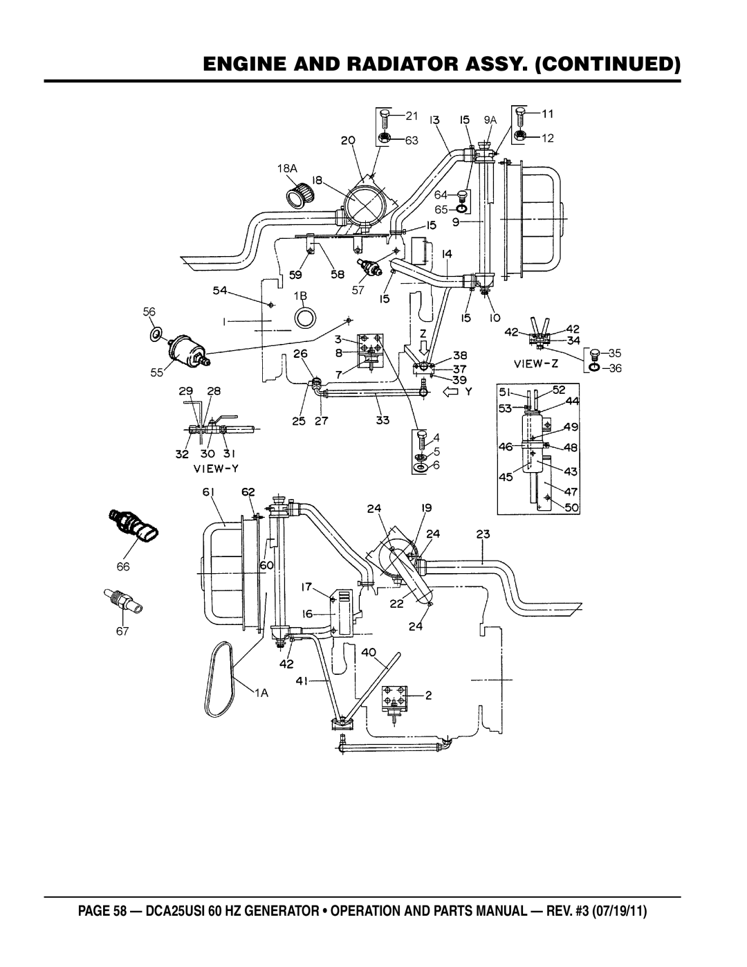
ENGINE AND RADIATOR ASSY. (continued)
page 58 — DCA25Usi 60 hz Generator • operation and parts manual — rev. #3 (07/19/11)
Page 57
Page 59
Page 58
Image 58
Page 57
Page 59
Contents
Parts List NO. M1871400104 parts list no. m1871400114c
Model dca25USI
Proposition 65 warning
Reporting Safety Defects
Administrator
Table of Contents
DCA25USI 60 Hz Generator
Choose from three easy options
SaFeTY messages
Safety Information
SaFeTY sYmBols
General saFeTY
GeneraTor saFeTY
Restricted. If the air fl ow is
Engine saFeTY
If operating in speed ranges above the maximum allowable
„ never use fuel as a cleaning agent
FUel saFeTY
ToWing saFeTY
From fuel vapors or if fuel is spilled on a hot engine
Power Cord/Cable safety
EleCTriCal saFeTY
Grounding safety
Death
BaTTerY saFeTY
EnvironmenTal saFeTY
Model
Specifications
Model Isuzu AA-4LE2 Tier 2 Certified
Dimensions
Dimensions
Installation
Typical Generator Grounding Application
Mounting
Outdoor Installation
Indoor Installation
Generator Grounding
General Information
Major Components
Item no
Generator Control Panel
Generator Control Panel
Engine Operating Panel
Terminal legs O and Ground are considered bonded grounds
Output Terminal Familiarization
Output Terminal Panel is provided with the following
Removing the Plastic Face Plate Hard Wire Hookup Panel
VAC Gfci Receptacles
Connecting Loads
Over Current Relay
Load Application
Single Phase Load
Three Phase Load
Type of Load
Generator Output Voltages
Voltage Selector Switch
Voltage Selector Switch Locking Button
Generator Amperage
AC Voltmeter Gauge Reading
How to Read the ac ammeter and ac voltage gauges
Generator OUTPUTS/gauge reading
AC Ammeter Gauge Reading
3Ø-240/139 Uvwo Terminal Output Voltages
Uvwo Terminal Output Voltages
3Ø-208V/1Ø-120V Uvwo Terminal Output Voltages
3Ø-480/277V Uvwo Terminal Output Voltages
1Ø-240/120V Uvwo Terminal Output Voltages
Lubrication Oil
Inspection/SETUP
Circuit Breakers
Fuel Check
Refueling Procedure
Only use #2 diesel fuel when refueling
Coolant Antifreeze/Summer Coolant/ Water
Cleaning the Radiator
Air Cleaner Fan Belt Tension
Operation in Freezing Weather
Wiring
Battery
Battery Cable Installation
Alternator
Starting
Before Starting
Engine’s exhaust contains harmful emissions
Coolant Temperature Gauge
Emergency Shutdown Procedure
Normal Shutdown Procedure
Never stop the engine suddenly except in an emergency
General Inspection Air Cleaner
Maintenance
Air Cleaner with Dust Indicator
Removing Water from the Fuel Tank
Cleaning Inside the Fuel Tank
Fuel Addition
Fuel Tank Inspection
Replacing Oil Filter
Radiator Cleaning
Check Oil Level
Flushing Out Radiator and Replacing Coolant
Trailer Maintenance
Trailer Maintenance
Coupler Type of hitch used on the trailer for towing
Hydraulic Surge Brakes
Brake Adjustment
Brakes
Actuator
Tire Wear/Inflation
Tires/Wheels/Lug Nuts
Suspension
Lug Nut Torque Requirements
Never use an pneumatic air gun to tighten wheel lug nuts
Trailer Wiring Diagram
Trailer/Towing Vehicle Wiring Diagram
Generator Wiring Diagram
Generator Wiring Diagram
Engine Wiring Diagram
Engine Wiring Diagram
Engine Wiring Diagram
Troubleshooting Generator
Symptom Possible Problem Solution
Page
Explanation of Code in Remarks Column
Suggested Spare Parts
Qty Description
Generator Assy
0601822630
B1110200602
7961025004
8001070003
Control box Assy
0021005080
M1215000612
0601808820
0601823240
Control box Assy
0601801041
0601808985 AC AMMETER, 0~50A/100A5A 0601801040
0601806859
0601840121
Engine and Radiator Assy
8944567411
B1925200254
897230-9390
M1305200304
Engine and Radiator Assy
M1312600204
M9602000003
0150000018
0199901600
Output Terminal Assy
M9220000104
M1230700003
M9220000004
0039308000
Battery Assy
M9103000304
0602220185
M9310500014
0602220920
Muffler Assy
M133200012
M1332000002
81000001 ~
M1335000103
Fuel Tank Assy
0605501071
M1365000302
0605505070
0605516090
Enclosure Assy
M1495000104
M1415000502
M1414000402
M1415100202
Enclosure Assy
27B M1495300604
M1445300103
27A M1495300504
M1445400103
Enclosure Assy
M9112100504
51A C9312500004
52A 0030006000
0601850097
Rubber Seals Assy
REMArks
Nameplate and Decals Assy
M1512400102
M1512400002
M11240000A
M11240010A
Terms and Conditions of Sale Parts
Freight Policy
Page
HERE’S HOW to GET Help
Top
Page
Image
Contents