Generator Control Panel
|
|
| 1 |
7 | INCREASE |
| DECREASE |
|
|
| 2 |
|
| V |
|
6 | U | OFF | W 3 |
|
|
|
OFF
5
4
10002000
STOP OPERATION
3000
START | R P M |
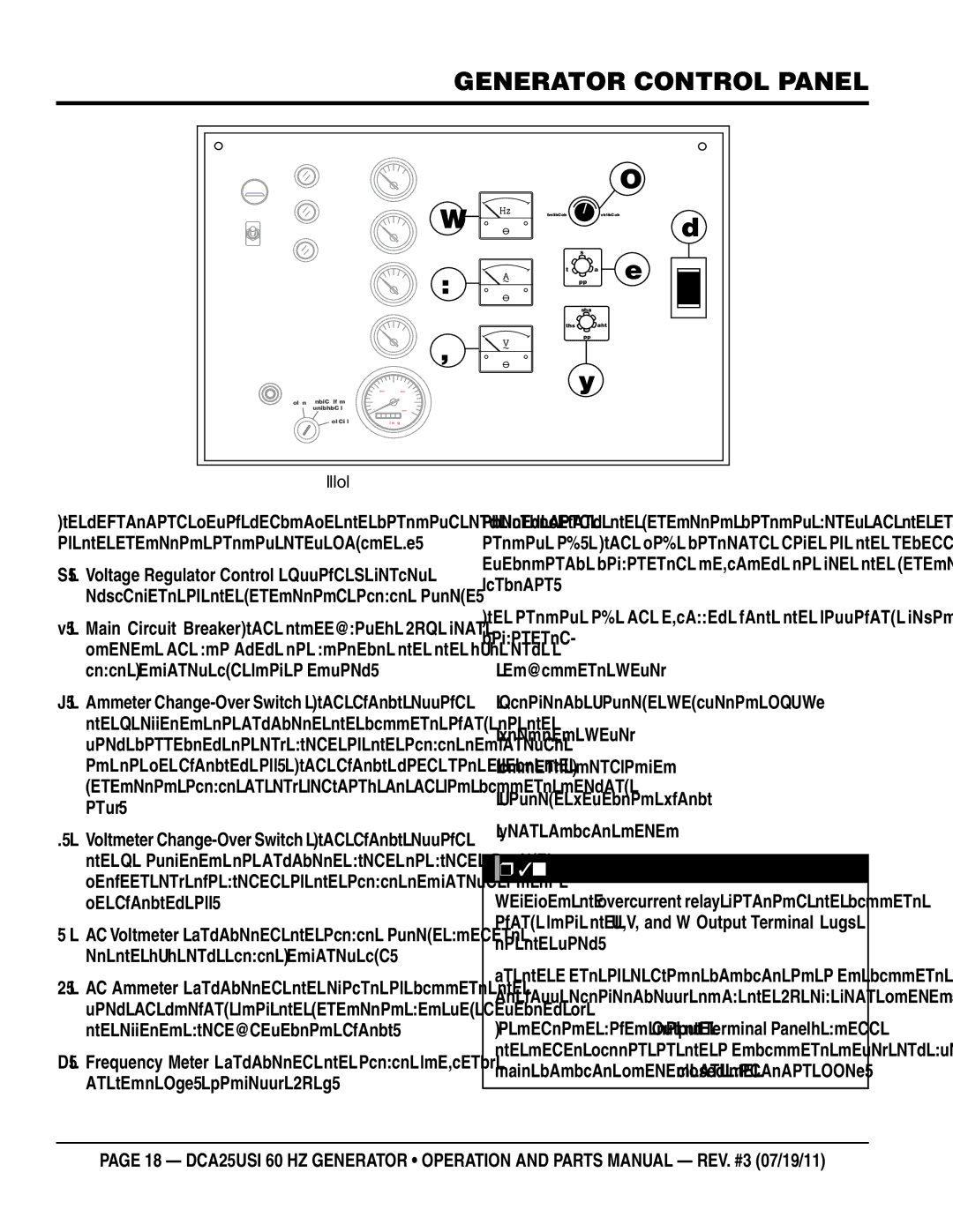
Figure 4. Generator Control Panel
The definitions below describe the controls and functions of the Generator Control Panel (Figure 4).
1.Voltage Regulator Control — Allows ±15% manual adjustment of the generator’s output voltage.
2.Main Circuit
3.Ammeter
4.Voltmeter
5.AC Voltmeter — Indicates the output voltage present at the U,V, and W Output Terminal Lugs.
6.AC Ammeter — Indicates the amount of current the load is drawing from the generator per leg selected by the ammeter
7.Frequency Meter — Indicates the output frequency in hertz (Hz). Normally 60 Hz.
Located behind the generator control panel is the Generator Control Box. This box contains some of the necessary electronic components required to make the generator function.
The Control Box is equipped with the following major components:
Automatic Voltage Regulator (AVR)
Starter Relay
Current Transformer
Voltage Selector Switch
Main Circuit Breaker
![]() NOTICE
NOTICE
Remember the overcurrent relay monitors the current flowing from the U,V, and W Output Terminal Lugs to the load.
In the event of a short circuit or over current condition, it will automatically trip the 60 amp main breaker.
To restore power to the Output Terminal Panel, press the reset button on the overcurrent relay and place the main circuit breaker in the closed position (ON).
page 18 — DCA25Usi 60 hz Generator • operation and parts manual — rev. #3 (07/19/11)