Model DCA25USIXF Model DCA25USI2XF
Diesel engine exhaust and some
Proposition 65 Warning
Table of Contents
Parts Ordering Procedures
Ordering parts has never been easier
Safety Information
Safety Messages
„ Always know the location of the nearest
General Safety
Generator Safety
fire extinguisher
Engine Safety
Before servicing equipment
„ Never use fuel as a cleaning agent
Fuel Safety
Towing Safety
3ECURE Portable Power Cables in Cable Tray with TIE wraps
Device. All installations should be
Electrical Safety
„ Never use gas piping as an electrical ground
Battery Safety
Environmental Safety
Specifications
Generator Specifications
Dimensions
Dimensions
Decals
Generator Decals
Decals
Installation
Typical Generator Grounding Application
Mounting
Outdoor Installation
Indoor Installation
Generator Grounding
Familiarization
General Information
Two auxilliary circuit breakers, 250V @50 amps
Components
Major Components
Generator Control Panel
Generator Control Panel
Engine Operating Panel
Fuel Gauge Indicates amount of diesel fuel available
Terminal legs Oand Ground are considered bonded grounds
Output Terminal Panel
Output Terminal Panel
Output Terminal Familiarization
120VAC Gfci Receptacles
F.C.I. Receptacle
Connecting Loads
Connecting Loads Over Current Relay
Three Phase Load
Single Phase Load
Load Application
Generator OutputVoltages
Voltage Selector Switch
Gauge READING/TERMINAL Panel Connections
Maximum Amps
Voltage selector switch
Reading Voltage
Uvwo Terminal Output Voltages
Three-Phase Position
Output Terminal Panel Connections
3Ø 240/139 Output Terminal Lug Voltages
Voltage Selector Switch 240/120V Single-Phase Position
3Ø 480/277 Output Terminal Lug Voltages
Lubrication Oil
Setup
Circuit Breakers
Fuel Check
Refueling Procedure
ONLY! use #2 diesel fuel when refueling
Mm when depressed with the thumb as shown below
Cleaning the Radiator
Air Cleaner Fan Belt Tension
Operation FreezingWeather
Wiring
Battery
Battery Cable Installation
Alternator
Engines exhaust contains harmful emissions
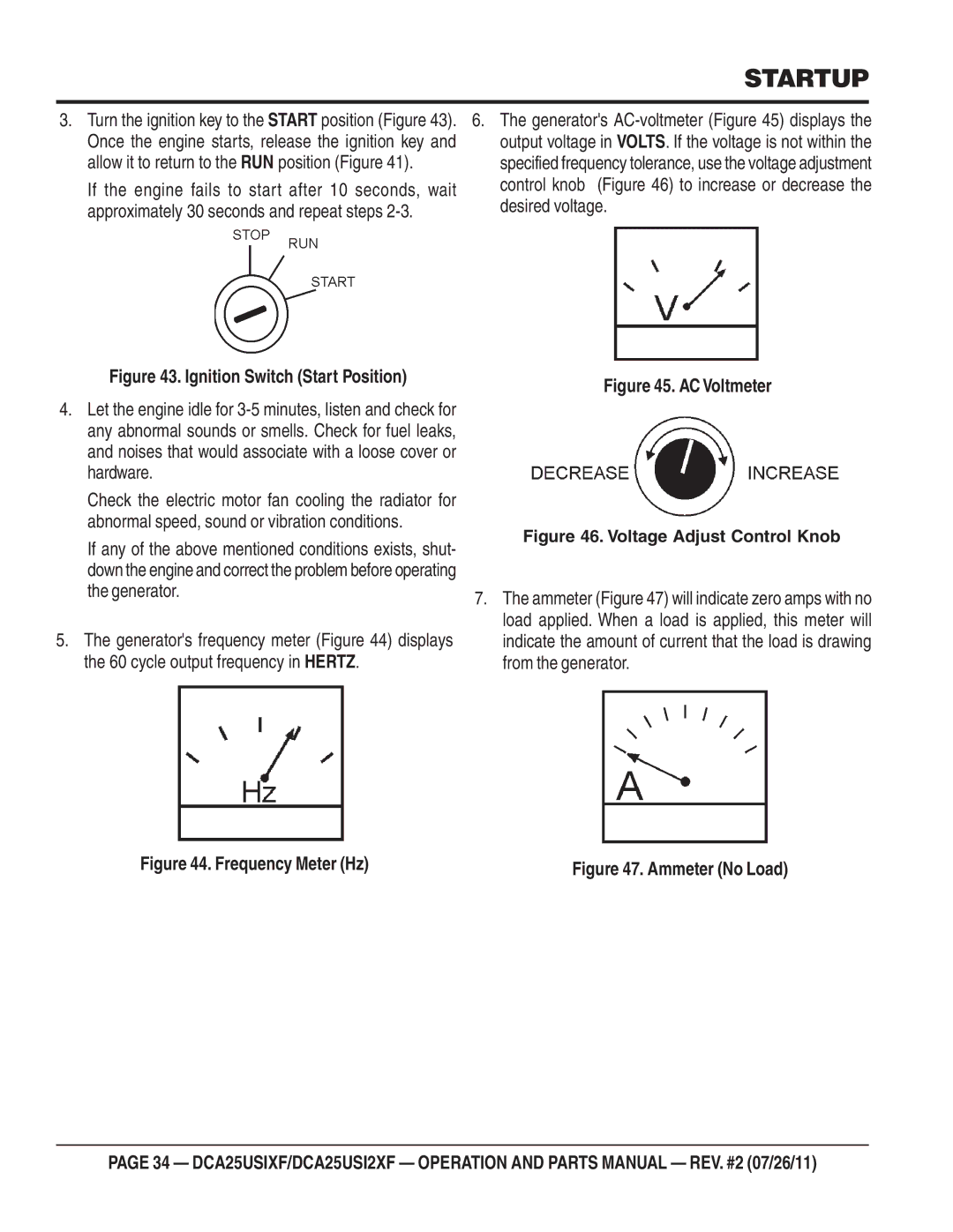
Startup
Before Starting
Direct exhaust away from nearby personnel
Ignition Switch Start Position
Oil Pressure Gauge
Shutdown
Normal Shut-down Procedure
Emergency Shut-down Procedure
Automatic Shut-down System
Maintenance
Air Removal
Cleaning the Fuel Strainer
Feed Pump Strainer Cleaning
Check Oil Level
Brakes
Trailer Maintenance
Brake Adjustment
Check the wheel and drum for free rotation
TireWear/Inflation
Tires/Wheels/Lug Nuts
Suspension
Lug Nut Torque Requirements
Start all wheel lug nuts by hand
Trailer Wiring Diagram
Trailer/Towing Vehicle Wiring Diagram
Engine Wiring Diagram
Engine Wiring Diagram
Engine Wiring Diagram
Generator Wiring Diagram
Generator Wiring Diagram
Engine does not start
Troubleshooting
Starter does not run
Stuck?
Generator Troubleshooting
Page
Explanation of Code in Remarks Column
Sample Parts List
Xxxxx only Not Used on
Suggested Spare Parts
Qty Description
Generator Assy
Generator Assy
Rectifier
Balancing Weight KIT
Field Assy
Surge Absorber
DCA25USIXF Control BOX Assy
Control BOX ASSY. Dcausixf only
Circuit BREAKER, 3P 60A
Decal Terminal Symbol
Control BOX
Machine Screw
DCA25USIXF Control BOX Assy
SWITCH, Panel Light
CHANGE-OVER SWITCH, Ammeter
Water Temperature Gauge
Toothed Washer
DCA25USI2XF Control BOX Assy
Control BOX ASSY. DCAUSI2XF only
Switch Cover
Selector Switch
Switch Bracket
CURRENTTRANSFORMER, 100/5A
DCA25USI2XF Control BOX Assy
Wire HARNESS, Generator
DCA25USIXF Engine and Radiator Assy
Engine and Radiator ASSY. Dcausixf only
INDICATOR, AIR Cleaner
AIR Cleaner
ELEMENT, AIR Cleaner
BRACKET, AIR Cleaner
DCA25USIXF Engine and Radiator Assy
Plug
UNIT, Water Temperature
Drain Joint
Ring
DCA25USI2XF Engine and Radiator Assy
Engine and Radiator ASSY. DCAUSI2XF only
ENGINE, Isuzu BV-4LE2
DCA25USI2XF Engine and Radiator Assy
M1316100603
Output Terminal Assy
Output Terminal Assy
TIE Screw
Terminal Panel
Output Terminal Bolt
Output Window
Battery Assy
Battery Assy
Battery Band
Battery
Battery Sheet
Battery Bolt SET
DCA25USIXF Muffler Assy
Muffler ASSY. DCA-25USIXF only
M1332000012
M1332000002
810000 ~8101465
M1335000103
DCA25USI2XF Muffler Assy
Muffler ASSY. DCA-25USI2XF only
Stay
Muffler
Gasket
Exhaust Pipe
Fuel Tank Assy
Fuel Tank Assy
Fuel Sender Unit
Fuel Tank
Fuel Tank CAP
Tank Support
DCA25USIXF Eclosure Assy
Enclosure ASSY. DCA25USIXF only
Environmental Tank
Base
Acoustic Sheet
Front Frame
DCA25USIXF Eclosure Assy
Rear Door
Rear Cover
Duct
Window Plate
DCA25USIXF Eclosure Assy
Support LEG
Fuel Leak Detected Switch
Bracket Stay
Bracket
DCA25USI2XF Eclosure Assy
Enclosure ASSY. DCA25USI2XF only
COVER, from Frame
Front Louver
DCA25USI2XF Eclosure Assy
M1443400103
M1443302203
34A M1493305104
35A M1493305204
DCA25USI2XF Eclosure Assy
Manual Holder
CLAMP, Manual Holder
Rubber Seals Assy
Rubber Seals Assy
0229200630
0229200790
0314500560
0228901220
Nameplate and Decals Assy
Name Plate Assy
Stripe
Decal MQ POWER, DCA25USI2
Plate MQ Power
Stripe Whisperwatt
Terms and Conditions of Sale Parts
Freightpolicy
Page
HERE’S HOW to GET Help