GENERATOR SHUT-DOWN PROCEDURES
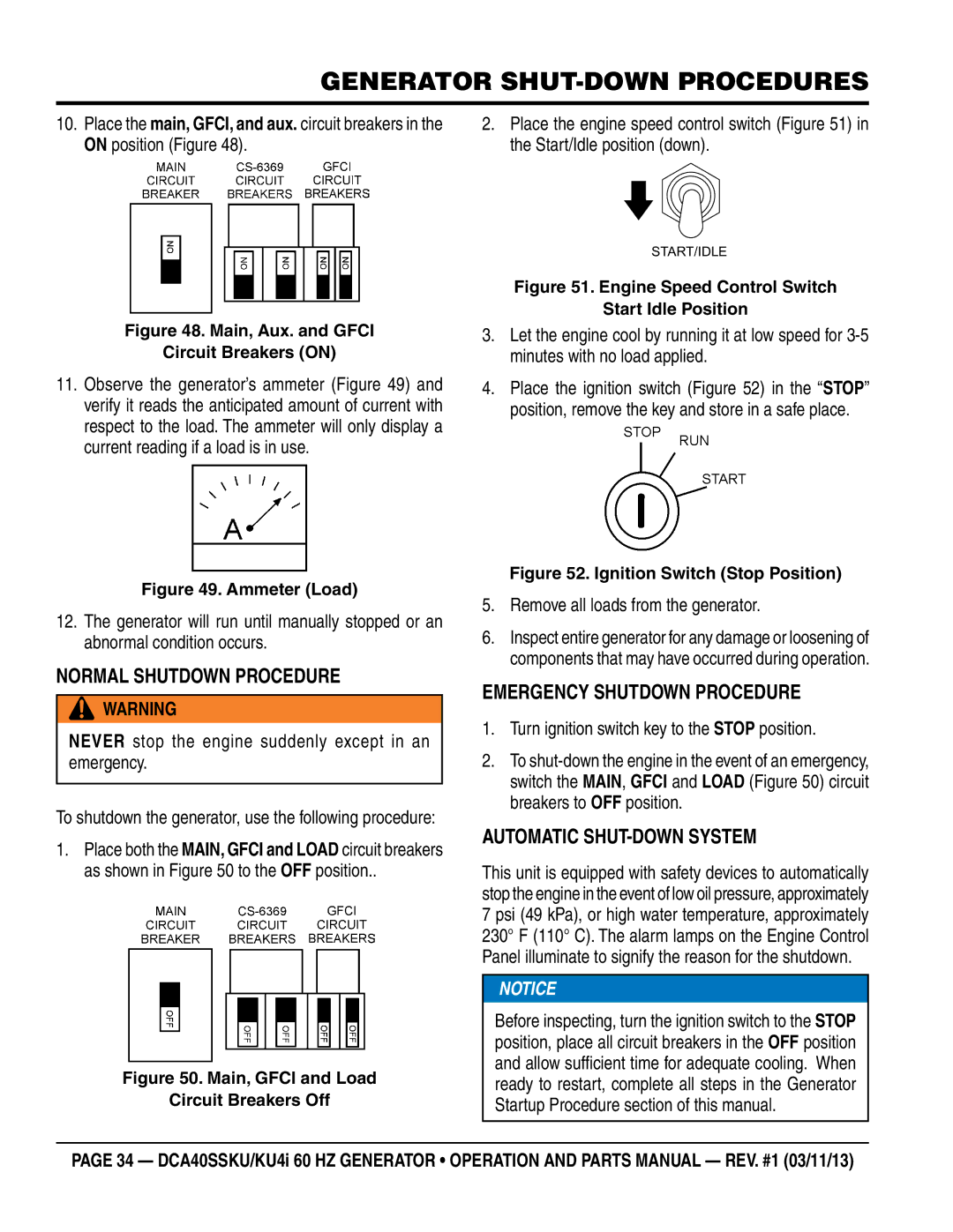
10.Place the main, GFCI, and aux. circuit breakers in the ON position (Figure 48).
2.Place the engine speed control switch (Figure 51) in the Start/Idle position (down).
Figure 48. Main, Aux. and GFCI
Circuit Breakers (ON)
11.Observe the generator’s ammeter (Figure 49) and verify it reads the anticipated amount of current with respect to the load. The ammeter will only display a current reading if a load is in use.
Figure 49. Ammeter (Load)
12.The generator will run until manually stopped or an abnormal condition occurs.
Normal Shutdown Procedure
![]() WARNING
WARNING
NEVER stop the engine suddenly except in an emergency.
To shutdown the generator, use the following procedure:
1.Place both the MAIN, GFCI and LOAD circuit breakers as shown in Figure 50 to the OFF position..
Figure 50. Main, GFCI and Load
Circuit Breakers Off
START/IDLE
Figure 51. Engine Speed Control Switch
Start Idle Position
3.Let the engine cool by running it at low speed for
4.Place the ignition switch (Figure 52) in the “STOP” position, remove the key and store in a safe place.
Figure 52. Ignition Switch (Stop Position)
5.Remove all loads from the generator.
6.Inspect entire generator for any damage or loosening of components that may have occurred during operation.
Emergency Shutdown Procedure
1.Turn ignition switch key to the STOP position.
2.To
Automatic Shut-down System
This unit is equipped with safety devices to automatically stop the engine in the event of low oil pressure, approximately 7 psi (49 kPa), or high water temperature, approximately 230° F (110° C). The alarm lamps on the Engine Control Panel illuminate to signify the reason for the shutdown.
![]() NOTICE
NOTICE
Before inspecting, turn the ignition switch to the STOP position, place all circuit breakers in the OFF position and allow sufficient time for adequate cooling. When ready to restart, complete all steps in the Generator Startup Procedure section of this manual.
page 34 — DCA40sskU/ku4i 60 hz Generator • operation and parts manual — rev. #1 (03/11/13)
