This Manual Must Accompany the Equipment AT ALL Times
Model DCA800SSK2
Proposition 65 Warning
Reporting Safety Defects
Administrator
Nhtsa
DCA800SSK2
Table of Contents
Ordering parts has never been easier
Parts Ordering Procedures
Safety Messages
Safety Information
General Safety
Generator Safety
Always know the location of the nearest
Before servicing equipment
Engine Safety
From fuel vapors or if fuel is spilled on a hot engine
Fuel Safety
Towing Safety
Never use fuel as a cleaning agent
Device. All installations should be
Electrical Safety
Grounding Safety
Power Cord/Cable Safety
Environmental Safety
Battery Safety
Komatsu SAA6D170E3
Specifications
Dimensions
Dimensions
Typical Generator Grounding Application
Installation
Generator Grounding
Outdoor Installation
Indoor Installation
Mounting
General Information
Item no
Major Components
Pilot Lamp Indicates the system is running
Generator Control Panel
Owing from the U,V, and W Output Terminal Lugs to the load
Engine Operating Panel
Air Filter Alarm When the air fi lter
Page
Output Terminal Panel Familiarization
Output Terminal Familiarization
Terminal legs O and Ground are considered bonded grounds
Over Current Relay
Connecting Loads
Single Phase Load
Three Phase Load
Load Application
Generator Amperage
Generator Outputs
Generator Output Voltages
Voltage ChangeOver Board
AC Ammeter Gauge Reading
HOW to Read the AC Ammeter and AC Voltage Gauges
Generator OUTPUTS/GAUGE Reading
AC Voltmeter Gauge Reading
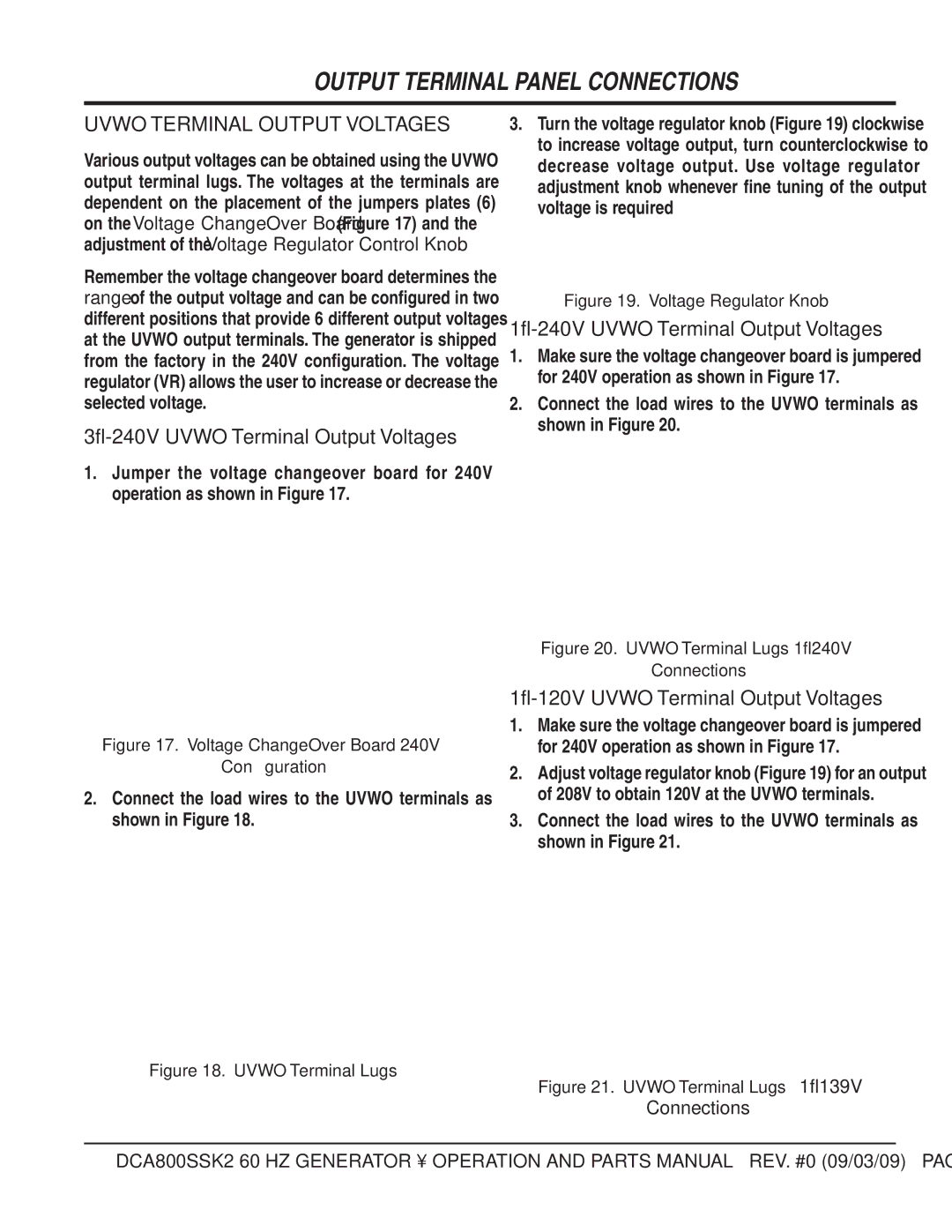
1Ø-240V Uvwo Terminal Output Voltages
Output Terminal Panel Connections
Uvwo Terminal Output Voltages
3Ø-240V Uvwo Terminal Output Voltages
3Ø-480V Uvwo Terminal Output Voltages
1Ø-480V Uvwo Terminal Output Voltages
1Ø-277V Uvwo Terminal Output Voltages
Fuel Check
INSPECTION/SETUP
Circuit Breakers
Lubrication OIL
Only use #2 diesel fuel when refueling
Refueling Procedure
Operation in Freezing Weather
Cleaning the Radiator
AIR Cleaner FAN Belt Tension
Coolant ANTIFREEZE/SUMMER COOLANT/ Water
Alternator
Battery
Battery Cable Installation
Wiring
Is lit on
Generator Startup Procedure Manual
Before Starting
Engine’s exhaust contains harmful emissions
Starting Manual
Place the engine speed switch in the LOW position Figure
Ammeter No Load
Verify that the main circuit breaker on lamp is lit on
Place the engine speed switch in the High position
Generator Startup Procedure Auto Mode
Starting Auto Mode
Before connecting this generator to any
Generator Shutdown Procedures
Normal Shutdown Procedure
Emergency Shutdown Procedure
Maintenance
General Inspection AIR Cleaner
Air Cleaner with Dust Indicator
Fuel Addition
Fuel Tank Inspection
AIR Removal
Flushing OUT Radiator and Replacing Coolant
Radiator Cleaning
Check OIL Level
Replacing Oil Filter
Battery Charger and Jacket Water Heater Power Connections
Trailer Maintenance
Trailer Maintenance
Coupler Type of hitch used on the trailer for towing
Electric Brakes
Brake Drums or discs, Linings, and Hoses
Air Leaks
TIRES/WHEELS/LUG Nuts
Tire Wear/Inflation
Suspension
Never use an pneumatic air gun to tighten wheel lug nuts
Lug Nut Torque Requirements
Trailer/Towing Vehicle Wiring Diagram
Trailer Wiring Diagram
Generator Wiring Diagram
Generator Wiring Diagram
Engine Wiring Diagram
Generator Wiring Diagram Main Breaker
Controller Wiring Diagram
Engine Wiring Diagram
Troubleshooting Generator
Adjust governor controller
Troubleshooting Engine Controller
Clean/repair radiator grill
Adjust governor actuator
Komatsu Engine Controller
Page
Explanation of Code in Remarks Column
Sample Parts List
To 3 units
Suggested Spare Parts
Generator Assy
Insulator Washer
Balancing Weight KIT
Field Assy
RESISTOR, 80W 50K Ω
Generator Assy
Stator Cover
Bearing Cover
Packing
Cover Bracket
Control Panel Assy
Control Panel
Circuit Breaker on Switch
Switch
Panel Light Switch
Control BOX Assy
Machine Screw
Control BOX
Ammeter Current Transformer
Electric Parts SET Panel
Control BOX Assy
Snap PIN
Change Terminal
Terminal Plate
Change Plate
Engine Assy
Hose
ENGINE, Komatsu SAA170E3
Engine Foot
Radiator Bracket
Engine Assy
Drain Joint
Hose Band
Hose Joint
Valve
Radiator ASSY. S/N 316346 and Above
Tube
Connector
Cushion
Clamp
Alternator ASSY. S/N 311209 and Above
PULLEY, NON Hardening
BELT, Alternator
ALTERNATOR, Assy
Theromostat ASSY. S/N 316346 and Above
SEAL, Thermostat
HOUSING, Thermostat
Plate
Thermostat
Water Pump Assy
311819 and Above
6240611302
315602 and Above
6162631515
Starter ASSY. S/N 316346 and Above
0164331645
6008133512
6221816810
0101061645
Engine Operating Panel Assy
Alarm Lamp
Battery Switch
Battery Switch Bracket
Engine Speed Switch
Output Terminal Assy
Output Terminal Cover
Output Terminal
Output Terminal Bracket
Terminal
Output Terminal Assy
Receptacle
Rubber Cushion
Battery Assy
Battery Bolt
Battery
Battery Sheet
Battery Band
Muffler Assy
Muffler
Exhaust Pipe
Outlet Pipe
Fuel Tank Assy
Fuel Gauge Hose
Fuel Tank
Fuel Tank CAP
Fuel Filter
Enclosure ASSY.#1
Enclosure ASSY. #1
Enclosure ASSY. #1
Filler Cover
Filler Bracket
Center Frame
Roof Panel
Enclosure ASSY. #2
Duct Cover
Rear Frame
Louver Panel
Rear Frame Cover
Enclosure ASSY. #2
Panel
Guide
Roof Panel Cover
Enclosure ASSY. #3
Duct
Splasher Panel
Side Panel
Side Door
Enclosure ASSY. #3
22A C5494405904
C5454300604
21A C5494405904
C5454300904
Rubber Seals Assy
0228901690
0228901750
0228901780
0228901800
Nameplate and Decals Assy
Output Terminal Group
Control Panel & BOX Group
Engine & Radiator Group
Decal Fuel Priming Engine Operating Panel Group
Nameplate and Decals Assy
Bonnet Group
Battery Group
Muffler Group
Fuel Tank Group
Nameplate and Decals Assy
C1552000403
Freight Policy
Terms and Conditions of Sale Parts
Page
HERE’S HOW to GET Help