LT12DAB specifications
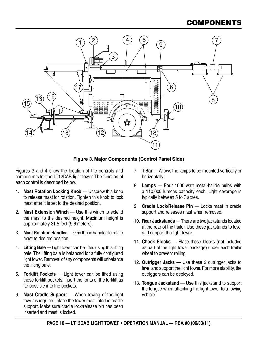
The Multiquip LT12DAB is an innovative and reliable light tower designed to deliver efficient lighting solutions for various outdoor applications. Known for its robust construction and user-friendly features, the LT12DAB is ideal for construction sites, events, and emergency situations, providing flexibility and performance in a compact package.One of the standout features of the LT12DAB is its powerful lighting system. It is equipped with four high-intensity LED lights, each delivering up to 12,000 lumens, ensuring ample illumination for expansive areas. The LED technology not only enhances visibility but also offers advantages in power consumption, resulting in reduced energy costs and longer operational life. The tower can be raised up to 30 feet, enabling it to cast a broad beam of light across large outdoor spaces.
The LT12DAB is built with advanced mobility in mind. It features a durable, weather-resistant frame that can withstand various environmental conditions, making it suitable for use in diverse locations. The all-terrain wheels provide enhanced maneuverability, allowing operators to transport the unit easily across job sites or uneven terrains. Additionally, the lightweight design ensures that it can be easily handled by a small crew.
Powering the LT12DAB is a reliable and fuel-efficient diesel generator that provides extended run times without frequent refueling. This generator not only supports the lighting system but can also power additional tools and equipment, adding versatility to its functionality. The unit is designed with low noise emissions, making it ideal for operation in noise-sensitive areas.
Ease of use is paramount in the design of the LT12DAB. The intuitive control panel allows users to operate the lights and generator effortlessly. The telescopic mast can be raised or lowered quickly, with safety features in place to prevent accidental collapse. Moreover, the integrated sensors monitor the oil levels and engine temperature, providing alerts for maintenance needs.
In summary, the Multiquip LT12DAB combines powerful lighting capabilities with robust construction and user-friendly features. Its mobility, energy efficiency, and reliability make it a valuable tool for any outdoor project, ensuring that worksites remain well-lit and safe, regardless of the conditions. Whether for construction, events, or emergencies, the LT12DAB stands out for its performance and adaptability, meeting the demands of today’s professional environments.

