Model R2000H
Proposition 65WARNING
Page
Table of Contents
Parts Ordering Procedures
Best Deal! Order via Internet Dealers Only
Order via Fax Dealers Only
25 x 7 x 7 in .5 x17.8 x17.8 cm
LH 9 in mm
RH 3.25 in mm LH 1.75 in mm
Drive to rear roll
R2000H Specifications Engine
R2000H Roller Dimensions
R2000H Dimensions
Seriously injured if you do not follow directions
Injury to yourself and others
Instructions
Always wear approved respiratory protection
Rules for Safe Operation
Always wear seat belts
Rules for Safe Operation
Emergencies
Never stand below roller when it is being lifted
Machine Safety Decals
Operation and Safety Decals
Recommended Slope
Do not operate this roller on slippery or wet surfaces
Tipping Rollover
Tipping Rollovers
Page
Roller Components
R2000H Roller Components
Free Wheel Engagement Pin
Tie-Down Transport Points
Attach a chain or suitable tie-down
R2000H Engine Components
Capacity is 400 cc Reference manufacturer engine
R2000H Inspection
Before Starting
Engine Oil Check
Water System Check
Sit down in the operators seat
Place the Choke Lever in the Closed position
Starting the Engine
R2000H Operation
Ignition Switch
Water Sprinklers Control
Place the transmission lever in the neutral position
Emergency Shut-Down
R2000H Maintenance
Lubrication
Hydrostatic Transmission
Drive Chains
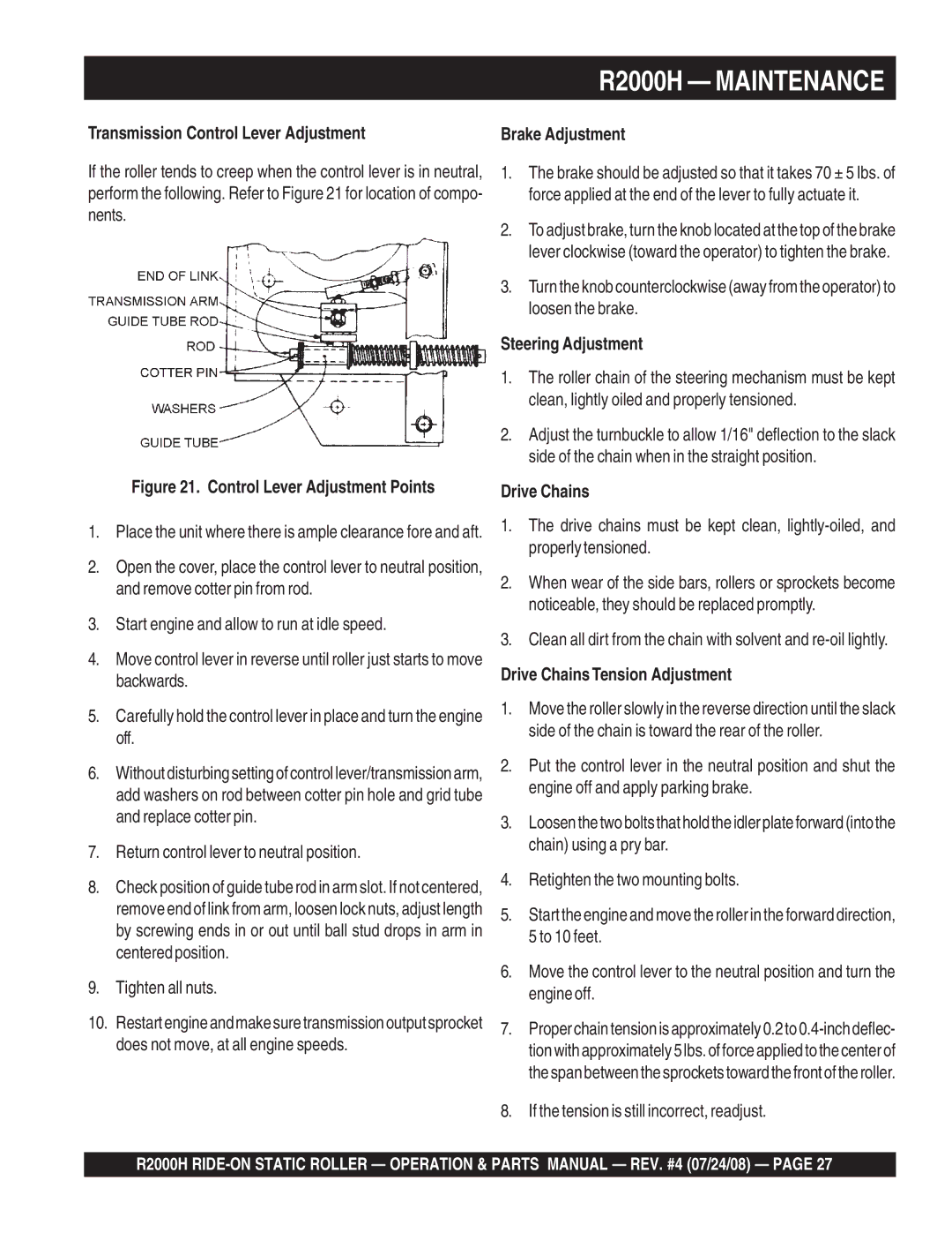
Transmission Control Lever Adjustment
Steering Adjustment
Drive Chains Tension Adjustment
TransmissionV-Belt Adjustment
Use a belt tension tester to check the belt tension
Scrapers, Cocoa Mats, and Sprinkler Bars
Roller Storage
R2000H Preparation for Long -TERM Storage
R2000H Troubleshooting Roller
Engine Troubleshooting
R2000H Troubleshooting Engine
Remarks Column
NO. Column
Part NO. Column
QTY. Column
R2000H Suggested Spare Parts
Name Plate and Decals
R2000H Name Plate and Decals
DECAL, MQ Multiquip
DECAL, MQ R2000H Left
DECAL, MQ R2000H Right
DECAL, MQ
Brake Assy
R2000H Brake Assy
Spacer
Adjustable Yoke
LEVER, Parking Brake
CAP Screw 5/16
Steering Assy
R2000H Steering Assy
Washer 5/8
CAP
Hexnut 5/8
Flatwasher 5/8
Chassis & Covers Assy
R2000H Chassis and Covers Assy
PLATE, Shifter
Main Body Frame
GUARD, Rear
PANEL, Left Side
Battery Assy
R2000H Battery Assy
RED
Battery
CLAMP, Battery
CAP Screw 3/8
Rear Drum Assy
R2000H Rear Drum Assy
Bearing
Sprocket 70 Tooth
SCREW, HEX 5/8
Drive System Assy
R2000H Drive System Assy
PULLEY, Engine 6 MM
Honda GX240K1QAE2
WASHER, Flat 3/8
Clip
Transmission Assy
R2000H Transmission Assy
LEVER, Free Flow Relief
Adjustment ROD
ROD, Adjustment
PUMP, Hydrostatic
Water System Assy
R2000H Water System Assy
CAP, Plastic Water Tank
TANK, Water
Washer 5/16 Flat W
Washer 5/16 Lock
AIR Cleaner Assy
Honda GX240K1QAE2 Engine AIR Cleaner Assy
Collar B, AIR Cleaner
COVER, AIR Cleaner
GROMMET, AIR Cleaner
COLLAR, AIR Cleaner
Camshaft Assy
Honda GX240K1QAE2 Engine Camshaft Assy
Lifter Valve
SPRING, Weight Return
ROD Push
ARM Valve Rocker
Carburetor Assy
Honda GX240K1QAE2 Engine Carburetor Assy
Float SET
PLATE, Lever Setting
Gasket SET
Valve SET, Float
Control Assy
Honda GX240K1QAE2 Engine Control Assy
SPRING, Throttle Return
ARM, Governor
ROD, Governor
SPRING, Governor
Crankcase Cover Assy
Honda GX240K1QAE2 Engine Crankcase Cover Assy
GASKET, Case Cover
WEIGHT, Governor
HOLDER, Governor Weight
PIN, Governor Weight
Crankshaft Assy
Honda GX240K1QAE2 Engine Crankshaft Assy
90745ZE2600 KEY 6.3 X 6.3 X 961006206000
WEIGHT, Balancer
Cylinder Barrel Assy
Honda GX240K1QAE2 Engine Cylinder Barrel Assy
OIL Seal
Switch ASSY., OIL Level
SHAFT, Governor ARM
BOLT, Drain Plug
Cylinder Head Assy
Honda GX240K1QAE2 Engine Cylinder Head Assy
GASKET, Cylinder Head
GUIDE, VALVE, OS, Optional
GUIDE, EX. VALVE, OS, Optional
CLIP, Valve Guide
FAN Cover Assy
Honda GX240K1QAE2 Engine FAN Cover Assy
GROMMET, Drain Hole
CLIP, Wire Harness
CLIP, Tube
Shroud
Flywheel Assy
Honda GX240K1QAE2 Engine Flywheel Assy
KEY, Special Woodruff
FAN, Cooling
Flywheel Comp
NUT, Special 16MM
Fuel Tank Assy
Honda GX240K1QAE2 Engine Fueltank Assy
FILTER, Fuel
Rubber Supporter 107MM
JOINT, Fuel Tank
GASKET, Fuel Filler CAP
Ignition Coil Assy
Honda GX240K1QAE2 Engine Ignition Coil Assy
HOLDER, Stop Switch Wire
CLAMP, Wire
GROMMET, Wire
WIRE, Stop Switch 370MM
Starter Motor Assy
Honda GX390K1QAE2 Starter Motor Assy
Clutch Overrunning
WIRE, Water Cover
Contactor Assy
Armature
Honda GX240K1QAE2 Control BOX Assy
FUSE, Blade 15A Alert UNIT, OIL
Control BOX Assy
CLIP, Purse Lock
TUBE, Fastener
Muffler Assy
Honda GX240K1QAE2 Engine Muffler Assy
PIPE, EX
Muffler
Protector COMP., Muffler
PROTECTOR, EX. Pipe
Piston Assy
Honda GX240K1QAE2 Engine Piston Assy
PISTON, Standard
BOLT, Connecting ROD
Ring SET, PISTON, STD
Ring SET, PISTON, 0.75, Optional
Recoil Starter Assy
Honda GX240K1QAE2 Engine Recoil Starter Assy
SPRING, Starter Return
PULLEY, Recoil Starter
RATCHET, Starter
SPRING, Friction
Engine Labels
Honda GX240K1QAE2 Engine Engine Labels
MARK, OIL ALERT, E
EMBLEM, Internal
LABEL, Caution
MARK, CHOKE, External
Terms and Conditions of Sale Parts
Page
Your Local Dealer is
HERE’S HOW to GET Help