PREPARING THE MAIN UNIT
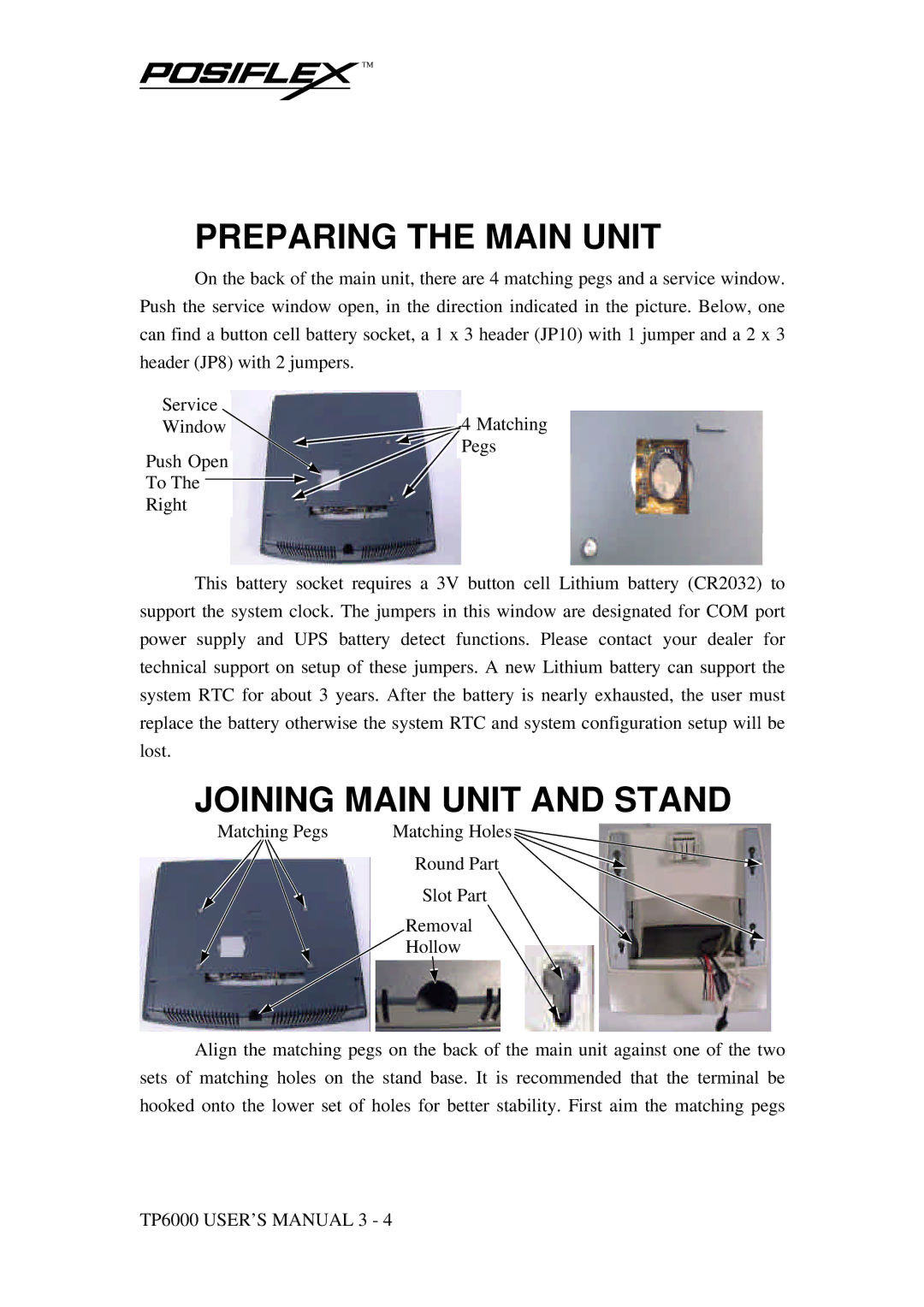
On the back of the main unit, there are 4 matching pegs and a service window. Push the service window open, in the direction indicated in the picture. Below, one can find a button cell battery socket, a 1 x 3 header (JP10) with 1 jumper and a 2 x 3 header (JP8) with 2 jumpers.
Service | 4 Matching |
Window | |
| Pegs |
Push Open
To The
Right
This battery socket requires a 3V button cell Lithium battery (CR2032) to support the system clock. The jumpers in this window are designated for COM port power supply and UPS battery detect functions. Please contact your dealer for technical support on setup of these jumpers. A new Lithium battery can support the system RTC for about 3 years. After the battery is nearly exhausted, the user must replace the battery otherwise the system RTC and system configuration setup will be lost.
JOINING MAIN UNIT AND STAND
Matching Pegs | Matching Holes | ||
|
| Round Part | |
|
| Slot Part | |
|
|
| |
|
| Removal |
|
|
| Hollow |
|
Align the matching pegs on the back of the main unit against one of the two sets of matching holes on the stand base. It is recommended that the terminal be hooked onto the lower set of holes for better stability. First aim the matching pegs
TP6000 USER’S MANUAL 3 - 4