marked “signal cable from POS Printer” at the rear of each cash drawer. The cable lengths for the two 8 pin plugs are different. Use the shorter one for the first cash drawer “CR1” and use the longer one for the second cash drawer “CR2” that will be controlled by the application software. Using this method, the TP6000 is capable of controlling two cash drawers independently through software command.
WALL MOUNTING
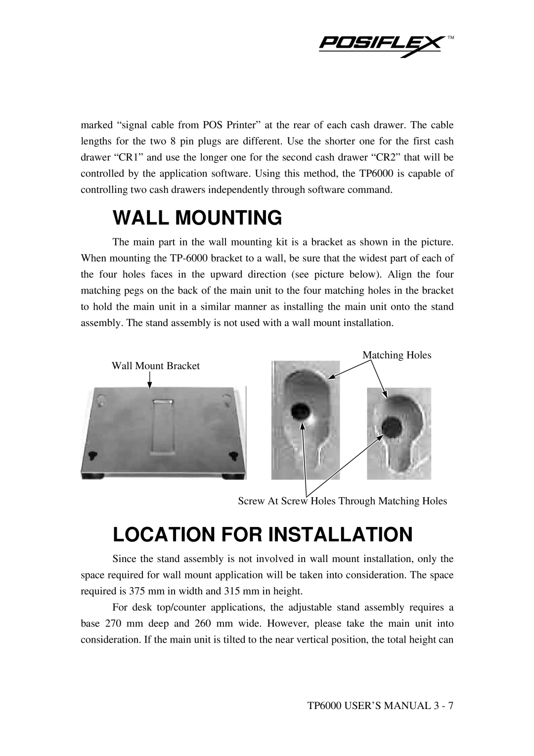
The main part in the wall mounting kit is a bracket as shown in the picture. When mounting the
Matching Holes
Wall Mount Bracket
Screw At Screw Holes Through Matching Holes
LOCATION FOR INSTALLATION
Since the stand assembly is not involved in wall mount installation, only the space required for wall mount application will be taken into consideration. The space required is 375 mm in width and 315 mm in height.
For desk top/counter applications, the adjustable stand assembly requires a base 270 mm deep and 260 mm wide. However, please take the main unit into consideration. If the main unit is tilted to the near vertical position, the total height can
TP6000 USER’S MANUAL 3 - 7