Operation
FRONT-PANEL CONTROLS AND INDICATORS
ENGLISH FRANÇAIS DEUTSCH NEDERLANDS ESPAÑOL ITALIANO PORTUGUÊS SVENSKA
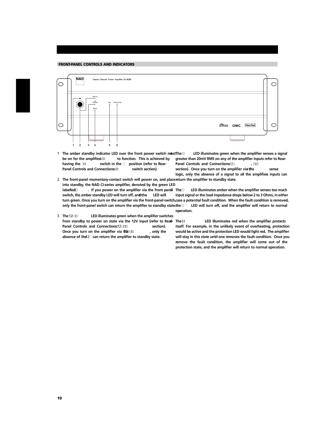
1The amber standby indicator LED over the front power switch must be on for the amplifier’s ATO Logic to function. This is achieved by having the “VACATION switch” in the ON position (refer to “Rear- Panel Controls and Connections”: VACATION switch section).
2The
3The
4The SENSE LED illuminates green when the amplifier senses a signal greater than 20mV RMS on any of the amplifier inputs refer to “Rear- Panel Controls and Connections”: SLEEP/WAKE, SENSE/DEFEAT section). Once you turn on the amplifier via the SLEEP/WAKE sense logic, only the absence of a signal to all the amplifier’s inputs can return the amplifier to standby state.
5The OMC LED illuminates amber when the amplifier senses too much input signal or the load impedance drops below 2 to 3 Ohms, in either case a potential fault condition. When the fault condition is removed, the OMC LED will turn off, and the amplifier will return to normal operation.
6The PROTECTION LED illuminates red when the amplifier protects itself. For example, in the unlikely event of overheating, protection would be active and the protection LED would light red. The amplifier will stay in this state until one removes the fault condition. Once you remove the fault condition, the amplifier will come out of the protection state, and the amplifier will return to normal operation.
10
