10
TOP EXIT / HORIZONTAL TERMINATION
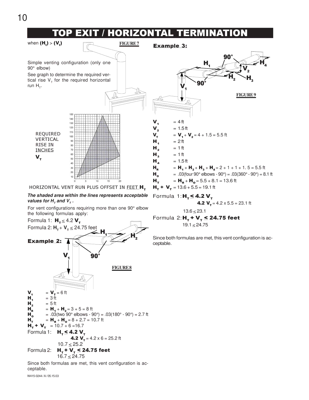
when (Ht) > (Vt) | FIGURE 7 | Example 3: |
|
|
Simple venting configuration (only one 90° elbow)
See graph to determine the required ver- tical rise VT for the required horizontal run HT.
V1 |
90° | H4 |
H1 | |
| V2 |
H2 | H |
90° | 3 |
| |
| FIGURE 9 |
REQUIRED
VERTICAL
RISE IN
INCHES
VT
HORIZONTAL VENT RUN PLUS OFFSET IN FEET HT
The shaded area within the lines represents acceptable values for HT and VT .
For vent configurations requiring more than one 90° elbow the following formulas apply:
Formula 1: HT < 4.2 | VT |
| |
Formula 2: HT + VT | < | 24.75 feet |
|
|
| H1 | H2 |
Example 2: |
|
| |
|
|
| |
V1 90°
FIGURE 8
V1 | = 4 ft |
V2 | = 1.5 ft |
VT | = V1 + V2 = 4 + 1.5 = 5.5 ft |
H1 | = 2 ft |
H2 | = 1 ft |
H3 | = 1 ft |
H4 | = 1.5 ft |
HR | = H1 + H2 + H3 + H4 = 2 + 1 + 1 + 1. 5 = 5.5 ft |
HO | = .03(four 90° elbows - 90°) = .03(360° - 90°) = 8.1 ft |
HT | = HR + HO = 5.5 + 8.1 = 13.6 ft |
HT + VT = 13.6 + 5.5 = 19.1 ft
Formula 1: HT < 4.2 VT
4.2VT = 4.2 x 5.5 = 23.1 ft
13.6< 23.1
Formula 2: HT + VT < 24.75 feet
19.1 < 24.75
Since both formulas are met, this vent configuration is ac- ceptable.
V1 | = VT = 6 ft |
H1 | = 3 ft |
H2 | = 5 ft |
HR | = H1 + H2 = 3 + 5 = 8 ft |
HO | = .03(two 90° elbows - 90°) = .03(180° - 90°) = 2.7 ft |
HT | = HR + HO = 8 + 2.7 = 10.7 ft |
HT + VT = 10.7 + 6 =16.7
Formula 1: HT < 4.2 VT
4.2VT = 4.2 x 6 = 25.2 ft
10.7< 25.2
Formula 2: HT + VT < 24.75 feet
16.7 < 24.75
Since both formulas are met, this vent configuration is ac- ceptable.