11
TOP EXIT VERTICAL TERMINATION
when (Ht) < (Vt) | Example 4: |
|
Simple venting configurations |
|
|
FIGURE 10 | FIGURE 11 | V2 |
| 90° | |
|
|
90° V1 H3  90°
90°
![]() H
H
H1  2
2
 90°
90°
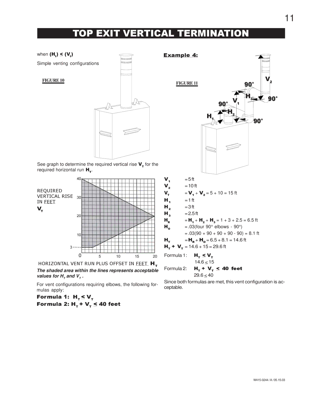
See graph to determine the required vertical rise VT for the required horizontal run HT.
REQUIRED
VERTICAL RISE
IN FEET
VT
HORIZONTAL VENT RUN PLUS OFFSET IN FEET HT
The shaded area within the lines represents acceptable values for HT and VT .
For vent configurations requiring elbows, the following for- mulas apply:
Formula 1: HT < VT
Formula 2: HT + VT < 40 feet
V1 | =5 ft |
V2 | =10 ft |
VT | = V1 + V2 = 5 + 10 = 15 ft |
H1 | =1 ft |
H2 | =3 ft |
H3 | =2.5 ft |
HR | = H1 + H2 + H3 = 1 + 3 + 2.5 = 6.5 ft |
HO | = .03(four 90° elbows - 90°) |
| = .03(90 + 90 + 90 + 90 - 90) = 8.1 ft |
HT | = HR + HO = 6.5 + 8.1 = 14.6 ft |
HT + VT = 14.6 + 15 = 29.6 ft
Formula 1: HT < VT 14.6 < 15
Formula 2: HT + VT < 40 feet
29.6 < 40
Since both formulas are met, this vent configuration is ac- ceptable.