12
TOP EXIT VERTICAL TERMINATION
when (Ht) > (Vt)
Simple venting configurations
See graph to determine the required vertical rise VT for the required horizontal run HT.
FIGURE 12
For vent configurations requiring elbows, the following for- mulas apply:
VT | = V1 + V2 + V3 = 2 + 1 + 1.5 = 4.5 ft |
H1 | =6 ft |
H2 | =2 ft |
HR | = H1 + H2 = 6 + 2 = 8 ft |
HO | = .03(four 90° elbows - 90°) |
| = .03(90 + 90 + 90 + 90 - 90) = 8.1 ft |
HT | = HR + HO = 8 + 8.1 = 16.1 ft |
HT + VT = 16.1 + 4.5 = 20.6 ft
Formula 1: HT < 3VT
3VT = 3 x 4.5 = 13.5 ft
16.1 > 13.5
Since this formula is not met, this vent configuration is unacceptable.
Formula 2: HT + VT < 40 feet
20.6 < 40
Since only formula 2 is met, this vent configuration is unac- ceptable and a new fireplace location or vent configuration will need to be established to satisfy both formulas.
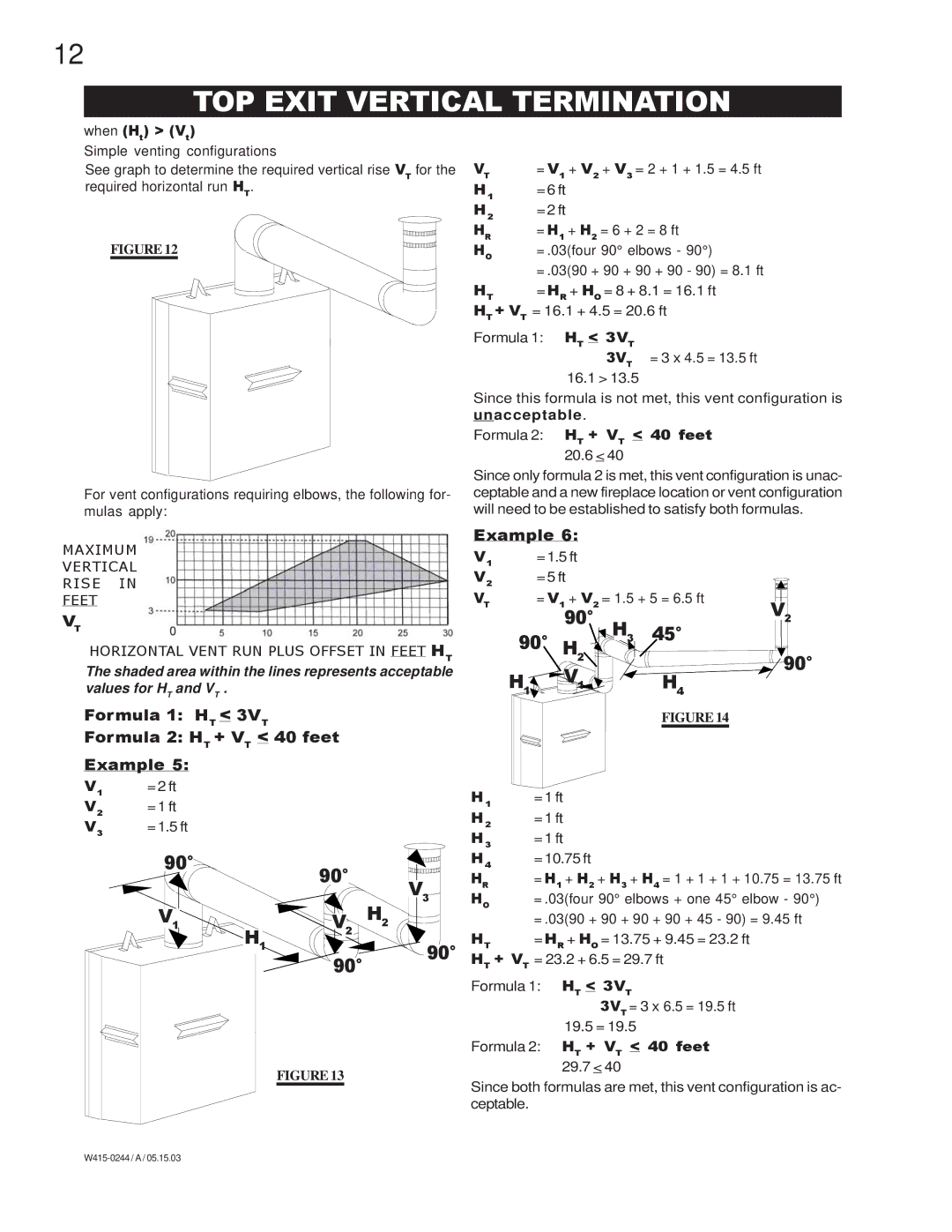
MAXIMUM
VERTICAL
RISE IN
FEET
VT
HORIZONTAL VENT RUN PLUS OFFSET IN FEET HT
The shaded area within the lines represents acceptable values for HT and VT .
Formula 1: HT < 3VT
Formula 2: HT + VT < 40 feet
Example 5:
V1 | =2 ft |
V2 | =1 ft |
V3 | =1.5 ft |
90° |
| 90° |
|
| |
|
| V3 |
V |
| H2 |
1 | H1 | V2 |
| 90° | |
|
| |
|
| 90° |
FIGURE 13
Example 6:
V1 | =1.5 ft |
|
V2 | =5 ft |
|
VT | = V1 + V2 | = 1.5 + 5 = 6.5 ft |
| 90° | V2 |
| H3 45° | |
90° H |
| |
| 2 | 90° |
| V1 | |
H | H | |
1 |
| 4 |
FIGURE 14
H1 | =1 ft |
H2 | =1 ft |
H3 | =1 ft |
H4 | =10.75 ft |
HR | = H1 + H2 + H3 + H4 = 1 + 1 + 1 + 10.75 = 13.75 ft |
HO | = .03(four 90° elbows + one 45° elbow - 90°) |
| = .03(90 + 90 + 90 + 90 + 45 - 90) = 9.45 ft |
HT | = HR + HO = 13.75 + 9.45 = 23.2 ft |
HT + VT = 23.2 + 6.5 = 29.7 ft
Formula 1: HT < 3VT
3VT = 3 x 6.5 = 19.5 ft
19.5 = 19.5
Formula 2: HT + VT < 40 feet
29.7 < 40
Since both formulas are met, this vent configuration is ac- ceptable.