18
FINISHING
DOOR REMOVAL & INSTALLATION
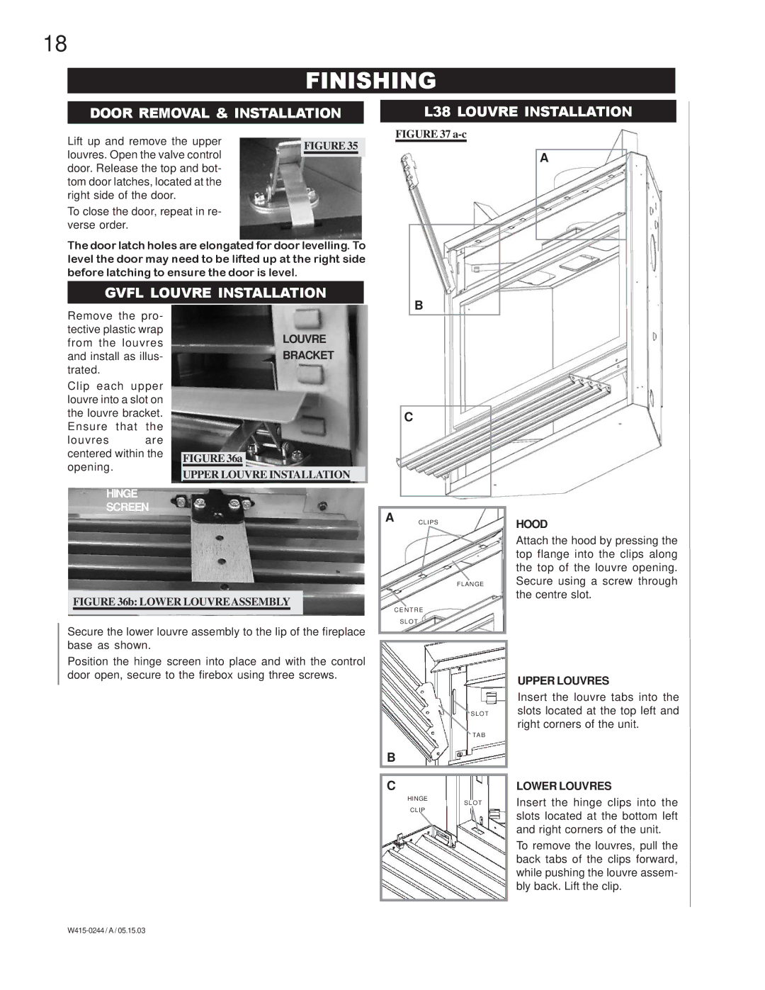
L38 LOUVRE INSTALLATION
Lift up and remove the upper | FIGURE 35 | |
louvres. Open the valve control | ||
| ||
| ||
door. Release the top and bot- |
| |
tom door latches, located at the |
| |
right side of the door. |
| |
To close the door, repeat in re- |
| |
verse order. |
|
The door latch holes are elongated for door levelling. To level the door may need to be lifted up at the right side before latching to ensure the door is level.
GVFL LOUVRE INSTALLATION
FIGURE 37 a-c
B
A
Remove the pro- tective plastic wrap from the louvres and install as illus- trated.
Clip each upper louvre into a slot on the louvre bracket. Ensure that the
louvres are centered within the opening.
HINGE
SCREEN
LOUVRE
BRACKET
FIGURE 36a
UPPER LOUVRE INSTALLATION
C
A CLIPS
HOOD
FIGURES37a-d
FIGURE 36b: LOWER LOUVRE ASSEMBLY
FLANGE
Attach the hood by pressing the top flange into the clips along the top of the louvre opening. Secure using a screw through the centre slot.
Secure the lower louvre assembly to the lip of the fireplace base as shown.
Position the hinge screen into place and with the control door open, secure to the firebox using three screws.
C E N T R E
S L O T
B
C
HINGE
CLIP
S L O T
TA B
S L O T
UPPER LOUVRES
Insert the louvre tabs into the slots located at the top left and right corners of the unit.
LOWER LOUVRES
Insert the hinge clips into the slots located at the bottom left and right corners of the unit.
To remove the louvres, pull the back tabs of the clips forward, while pushing the louvre assem- bly back. Lift the clip.
