CHAPTER 4 CIRCUIT CARD INFORMATION
List of Required Circuit Card
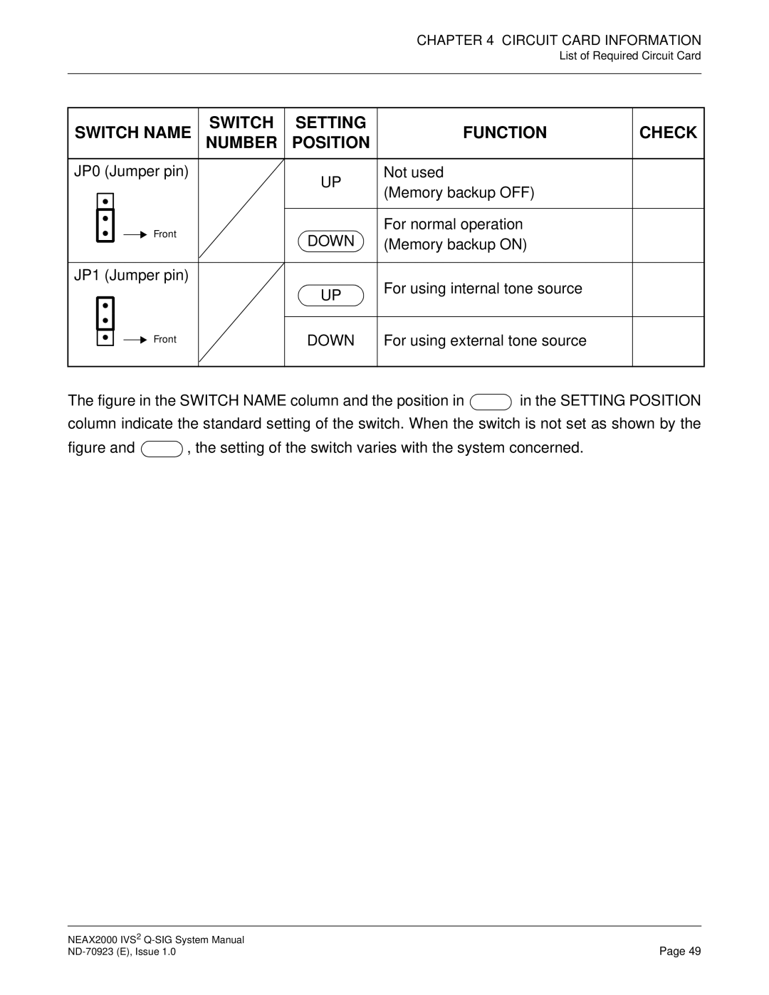
SWITCH NAME | SWITCH | SETTING | FUNCTION | CHECK | |
NUMBER | POSITION | ||||
|
|
| |||
JP0 (Jumper pin) |
| UP | Not used |
| |
|
| (Memory backup OFF) |
| ||
|
|
|
| ||
Front |
| DOWN | For normal operation |
| |
| (Memory backup ON) |
| |||
|
|
| |||
JP1 (Jumper pin) |
|
| For using internal tone source |
| |
|
| UP |
| ||
|
|
|
| ||
Front |
| DOWN | For using external tone source |
|
The figure in the SWITCH NAME column and the position in  in the SETTING POSITION column indicate the standard setting of the switch. When the switch is not set as shown by the
figure and  , the setting of the switch varies with the system concerned.
NEAX2000 IVS2 | Page 49 |