CHAPTER 4 CIRCUIT CARD INFORMATION
List of Required Circuit Card
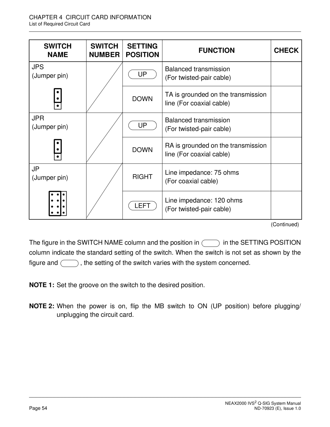
SWITCH | SWITCH | SETTING | FUNCTION | CHECK | ||||||
NAME | NUMBER | POSITION | ||||||||
|
| |||||||||
|
|
|
|
|
|
|
|
|
| |
JPS |
|
| UP | Balanced transmission |
| |||||
(Jumper pin) |
|
|
| |||||||
|
| (For |
| |||||||
|
|
|
|
|
|
|
|
| ||
|
|
|
|
|
|
|
|
|
| |
|
|
|
|
|
|
| DOWN | TA is grounded on the transmission |
| |
|
|
|
|
|
|
|
| |||
|
|
|
|
|
|
| line (For coaxial cable) |
| ||
|
|
|
|
|
|
|
|
| ||
|
|
|
|
|
|
|
|
|
| |
|
|
|
|
|
|
|
|
|
| |
JPR |
|
| UP | Balanced transmission |
| |||||
(Jumper pin) |
|
|
| |||||||
|
| (For |
| |||||||
|
|
|
|
|
|
|
|
| ||
|
|
|
|
|
|
|
|
|
| |
|
|
|
|
|
|
| DOWN | RA is grounded on the transmission |
| |
|
|
|
|
|
|
|
| |||
|
|
|
|
|
|
| line (For coaxial cable) |
| ||
|
|
|
|
|
|
|
|
| ||
|
|
|
|
|
|
|
|
|
| |
|
|
|
|
|
|
|
|
|
| |
JP |
|
|
| Line impedance: 75 ohms |
| |||||
(Jumper pin) |
|
| RIGHT |
| ||||||
|
| (For coaxial cable) |
| |||||||
|
|
|
|
|
|
|
|
| ||
|
|
|
|
|
|
|
|
|
| |
|
|
|
|
|
|
| LEFT | Line impedance: 120 ohms |
| |
|
|
|
|
|
|
| (For |
| ||
|
|
|
|
|
|
|
|
| ||
|
|
|
|
|
|
|
|
|
| |
|
|
|
|
|
|
|
|
|
| |
|
|
|
|
|
|
|
|
| (Continued) | |
The figure in the SWITCH NAME column and the position in  in the SETTING POSITION
column indicate the standard setting of the switch. When the switch is not set as shown by the
figure and  , the setting of the switch varies with the system concerned.
NOTE 1: Set the groove on the switch to the desired position.
NOTE 2: When the power is on, flip the MB switch to ON (UP position) before plugging/ unplugging the circuit card.
Page 54 | NEAX2000 IVS2 |