CHAPTER 2 INSTALLATION
Installation Procedure
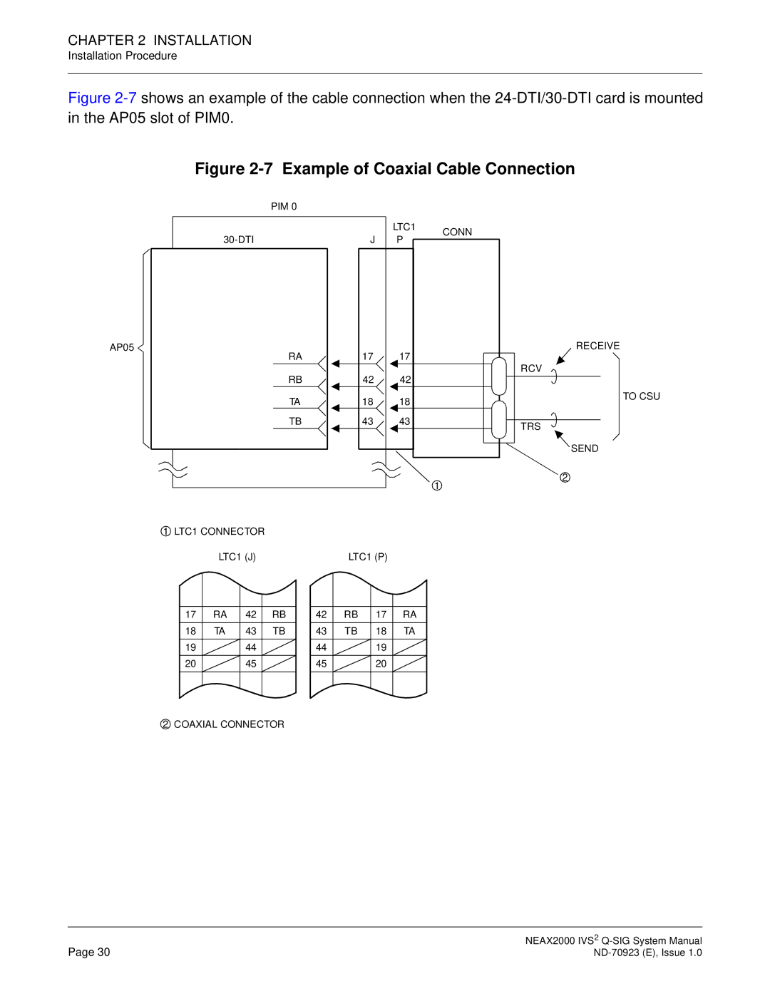
Figure 2-7 shows an example of the cable connection when the 24-DTI/30-DTI card is mounted in the AP05 slot of PIM0.
Figure 2-7 Example of Coaxial Cable Connection
| PIM 0 |
| |
| LTC1 | CONN | |
J P | |||
|
AP05 |
| 17 |
| 17 |
| RECEIVE | |||
| RA |
|
|
|
| ||||
| RB |
| 42 |
| 42 |
| RCV | ||
|
|
|
| TO CSU | |||||
| |||||||||
| TA |
| 18 |
| 18 |
|
| ||
|
|
|
|
| |||||
| TB | 43 |
| 43 |
|
|
| ||
TRS | |||||||||
|
|
|
|
|
|
| |||
|
|
|
|
|
|
| |||
SEND
![]() 2
2![]()
![]() 1
1![]()
![]() 1
1![]() LTC1 CONNECTOR
LTC1 CONNECTOR
LTC1 (J)
17 | RA | 42 | RB |
18 | TA | 43 | TB |
19 |
| 44 |
|
20 |
| 45 |
|
LTC1 (P)
42 | RB | 17 | RA |
43 | TB | 18 | TA |
44 |
| 19 |
|
45 |
| 20 |
|
![]() 2
2![]() COAXIAL CONNECTOR
COAXIAL CONNECTOR
Page 30 | NEAX2000 IVS2 |