CHAPTER 4 CIRCUIT CARD INFORMATION
List of Required Circuit Card
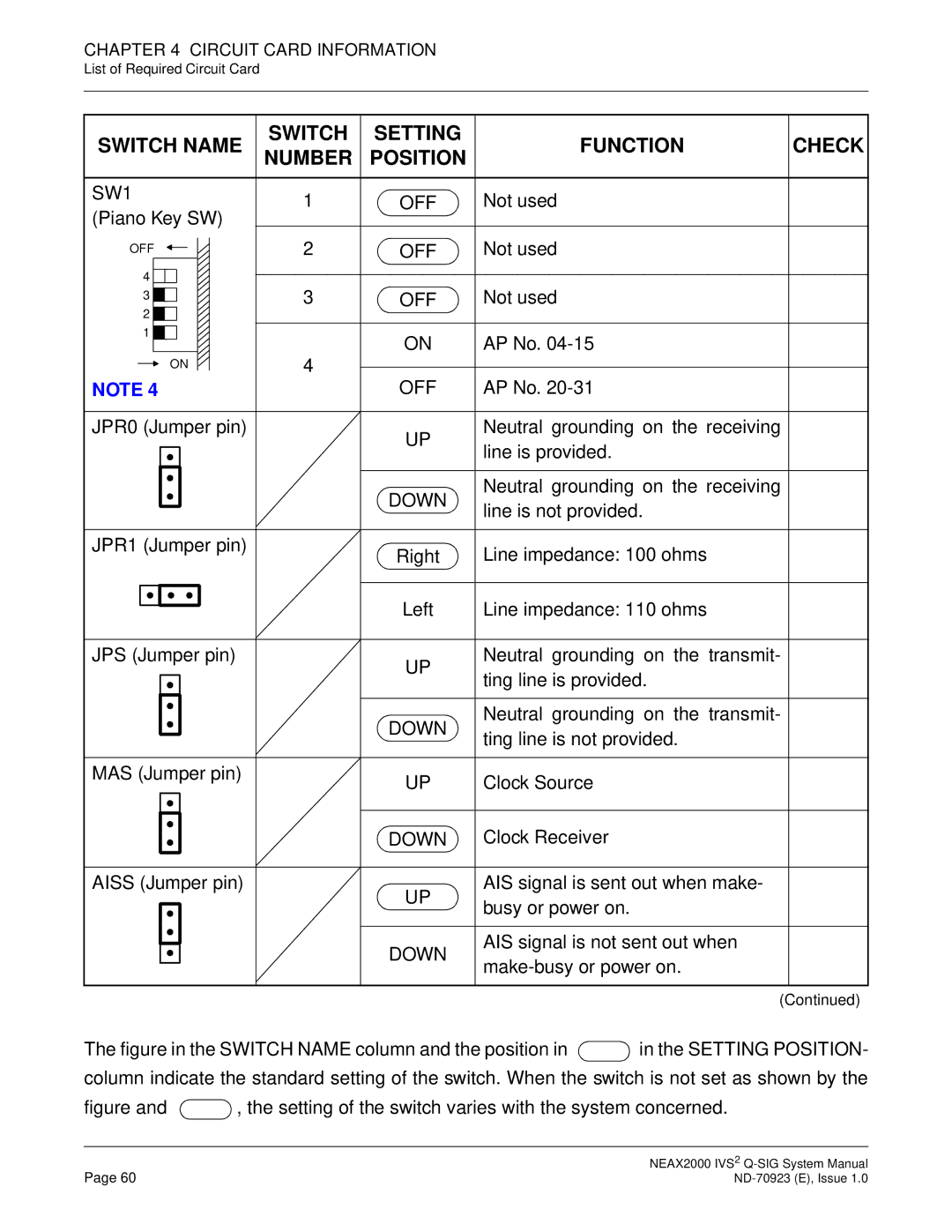
SWITCH NAME | SWITCH | SETTING | FUNCTION | CHECK | |||||||||||||
NUMBER | POSITION | ||||||||||||||||
|
|
|
|
|
|
|
|
|
|
|
|
|
|
| |||
|
|
|
|
|
|
|
|
|
|
|
|
|
|
|
|
| |
SW1 | 1 | OFF | Not used |
| |||||||||||||
(Piano Key SW) |
| ||||||||||||||||
|
|
|
| ||||||||||||||
OFF |
|
|
|
|
|
|
| 2 | OFF | Not used |
| ||||||
|
|
|
|
|
|
|
|
| |||||||||
|
|
|
|
|
|
|
| ||||||||||
4 |
|
|
|
|
|
|
|
|
|
|
|
|
|
| |||
|
|
|
|
|
|
|
|
|
|
|
|
|
| ||||
3 |
| Not used |
| ||||||||||||||
3 |
|
|
|
|
|
|
|
|
|
| OFF |
| |||||
|
|
|
|
|
|
|
|
|
|
| |||||||
2 |
|
|
|
|
|
|
|
|
|
|
|
|
|
| |||
|
|
|
|
|
|
|
|
|
|
|
|
|
| ||||
1 |
|
|
|
|
|
|
|
|
|
|
|
|
|
| |||
|
|
|
|
|
|
|
|
|
| 4 | ON | AP No. |
| ||||
|
|
|
|
|
|
|
|
|
|
| |||||||
|
|
|
|
|
|
|
|
|
|
|
|
|
| ||||
|
|
|
| ON |
|
|
|
|
|
|
|
| |||||
|
|
|
|
|
|
|
|
|
|
| |||||||
OFF | AP No. |
| |||||||||||||||
|
|
|
|
|
| ||||||||||||
NOTE 4 |
|
| |||||||||||||||
|
|
|
|
|
|
|
|
|
|
|
|
|
|
|
|
| |
JPR0 (Jumper pin) |
| UP | Neutral grounding on the receiving |
| |||||||||||||
|
|
|
|
|
|
|
|
|
|
|
|
|
| line is provided. |
| ||
|
|
|
|
|
|
|
|
|
|
|
|
|
|
|
| ||
|
|
|
|
|
|
|
|
|
|
|
|
|
|
|
|
| |
|
|
|
|
|
|
|
|
|
|
|
|
|
|
|
|
| |
|
|
|
|
|
|
|
|
|
|
|
|
|
| DOWN | Neutral grounding on the receiving |
| |
|
|
|
|
|
|
|
|
|
|
|
|
|
| line is not provided. |
| ||
|
|
|
|
|
|
|
|
|
|
|
|
|
|
| |||
|
|
|
|
|
|
|
|
|
|
|
|
|
|
|
| ||
|
|
|
|
|
|
|
|
|
|
|
|
|
|
|
|
| |
JPR1 (Jumper pin) |
| Right | Line impedance: 100 ohms |
| |||||||||||||
|
|
|
|
|
|
|
|
|
|
|
|
|
|
| |||
|
|
|
|
|
|
|
|
|
|
|
|
|
|
|
|
| |
|
|
|
|
|
|
|
|
|
|
|
|
|
| Left | Line impedance: 110 ohms |
| |
|
|
|
|
|
|
|
|
|
|
|
|
|
|
| |||
|
|
|
|
|
|
|
|
|
|
|
|
|
|
| |||
|
|
|
|
|
|
|
|
|
|
|
|
|
|
|
|
| |
JPS (Jumper pin) |
| UP | Neutral grounding on the transmit- |
| |||||||||||||
|
|
|
|
|
|
|
|
|
|
|
|
|
| ting line is provided. |
| ||
|
|
|
|
|
|
|
|
|
|
|
|
|
|
|
| ||
|
|
|
|
|
|
|
|
|
|
|
|
|
|
|
|
| |
|
|
|
|
|
|
|
|
|
|
|
|
|
|
|
|
| |
|
|
|
|
|
|
|
|
|
|
|
|
|
| DOWN | Neutral grounding on the transmit- |
| |
|
|
|
|
|
|
|
|
|
|
|
|
|
| ting line is not provided. |
| ||
|
|
|
|
|
|
|
|
|
|
|
|
|
|
| |||
|
|
|
|
|
|
|
|
|
|
|
|
|
|
|
| ||
|
|
|
|
|
|
|
|
|
|
|
|
|
|
|
|
| |
MAS (Jumper pin) |
| UP | Clock Source |
| |||||||||||||
|
|
|
|
|
|
|
|
|
|
|
|
|
|
| |||
|
|
|
|
|
|
|
|
|
|
|
|
|
|
|
|
| |
|
|
|
|
|
|
|
|
|
|
|
|
|
| DOWN | Clock Receiver |
| |
|
|
|
|
|
|
|
|
|
|
|
|
|
|
|
|
| |
AISS (Jumper pin) |
| UP | AIS signal is sent out when make- |
| |||||||||||||
|
|
|
|
|
|
|
|
|
|
|
|
|
| busy or power on. |
| ||
|
|
|
|
|
|
|
|
|
|
|
|
|
|
|
| ||
|
|
|
|
|
|
|
|
|
|
|
|
|
|
|
|
| |
|
|
|
|
|
|
|
|
|
|
|
|
|
| DOWN | AIS signal is not sent out when |
| |
|
|
|
|
|
|
|
|
|
|
|
|
|
|
| |||
|
|
|
|
|
|
|
|
|
|
|
|
|
|
| |||
|
|
|
|
|
|
|
|
|
|
|
|
|
|
|
| ||
|
|
|
|
|
|
|
|
|
|
|
|
|
|
|
|
| |
|
|
|
|
|
|
|
|
|
|
|
|
|
|
| (Continued) | ||
The figure in the SWITCH NAME column and the position in  in the SETTING POSITION- column indicate the standard setting of the switch. When the switch is not set as shown by the
figure and  , the setting of the switch varies with the system concerned.
Page 60 | NEAX2000 IVS2 |