PlasmaSync 3300 specifications
The NEC PlasmaSync 3300 is a robust and versatile display solution that emerged as a significant advancement in the realm of large-scale visual communication. Designed primarily for commercial applications, the PlasmaSync 3300 caters to various environments, including corporate settings, classrooms, control rooms, and public displays. This model stands out with its impressive screen size, exceptional image quality, and innovative features that enhance user experience.One of the defining characteristics of the NEC PlasmaSync 3300 is its large 33-inch screen, which provides ample space for displaying high-resolution content. With a native resolution of 1366 x 768 pixels, the display ensures a clear and vibrant presentation of visuals, making it perfect for multimedia presentations, graphic displays, and video playback. The model’s high brightness capability significantly enhances visibility, making it suitable for well-lit environments and high-traffic areas.
The PlasmaSync 3300 incorporates advanced plasma technology that contributes to stunning color accuracy and a wide color gamut. This ensures that images are not only vivid but also true to life, making it ideal for applications where color precision is paramount, such as in marketing and design presentations. Moreover, the display features a wide viewing angle, allowing viewers to enjoy consistent image quality from different positions within the room.
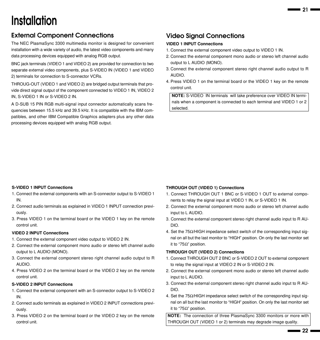
In addition to its impressive visual capabilities, the NEC PlasmaSync 3300 is designed with ease of use and installation in mind. It comes equipped with multiple input options, including VGA, DVI, and composite video connections, providing flexibility in integrating with various content sources. This extensive connectivity makes it compatible with a wide array of multimedia devices, such as computers, DVD players, and cameras, enabling seamless content sharing.
Another noteworthy feature of the PlasmaSync 3300 is its reliability and longevity. The plasma technology is known for its durability, and this model is no exception. It is built to withstand continuous operation, making it suitable for environments that require extended hours of use. Additionally, the NEC PlasmaSync 3300 offers energy-efficient features, helping to reduce power consumption and operating costs.
In summary, the NEC PlasmaSync 3300 is a powerful and feature-rich display solution that excels in delivering high-quality visuals for commercial applications. With its superior image clarity, extensive connectivity options, and reliable performance, it stands as an exemplary choice for those seeking a professional-grade plasma display. Whether for corporate presentations, educational purposes, or public information displays, the PlasmaSync 3300 meets various needs while providing stunning visual experiences.

