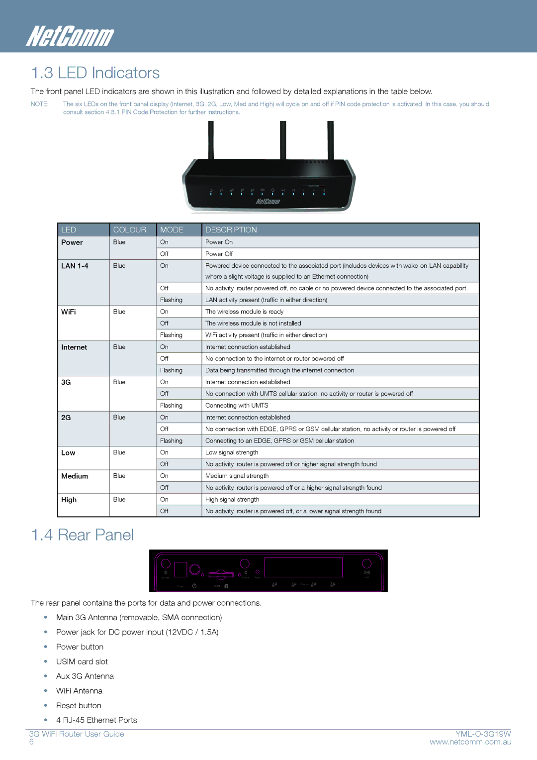
1.3 LED Indicators
The front panel LED indicators are shown in this illustration and followed by detailed explanations in the table below.
NOTE: | The six LEDs on the front panel display (Internet, 3G, 2G, Low, Med and High) will cycle on and off if PIN code protection is activated. In this case, you should |
| consult section 4.3.1 PIN Code Protection for further instructions. |
LED
COLOUR
MODE
DESCRIPTION
Power | Blue | On | Power On |
|
|
|
|
|
| Off | Power Off |
|
|
|
|
LAN | Blue | On | Powered device connected to the associated port (includes devices with |
|
|
| where a slight voltage is supplied to an Ethernet connection) |
|
|
|
|
|
| Off | No activity, router powered off, no cable or no powered device connected to the associated port. |
|
|
|
|
|
| Flashing | LAN activity present (traffic in either direction) |
|
|
|
|
WiFi | Blue | On | The wireless module is ready |
|
|
|
|
|
| Off | The wireless module is not installed |
|
|
|
|
|
| Flashing | WiFi activity present (traffic in either direction) |
|
|
|
|
Internet | Blue | On | Internet connection established |
|
|
|
|
|
| Off | No connection to the internet or router powered off |
|
|
|
|
|
| Flashing | Data being transmitted through the internet connection |
|
|
|
|
3G | Blue | On | Internet connection established |
|
|
|
|
|
| Off | No connection with UMTS cellular station, no activity or router is powered off |
|
|
|
|
|
| Flashing | Connecting with UMTS |
|
|
|
|
2G | Blue | On | Internet connection established |
|
|
|
|
|
| Off | No connection with EDGE, GPRS or GSM cellular station, no activity or router is powered off |
|
|
|
|
|
| Flashing | Connecting to an EDGE, GPRS or GSM cellular station |
|
|
|
|
Low | Blue | On | Low signal strength |
|
|
|
|
|
| Off | No activity, router is powered off or higher signal strength found |
|
|
|
|
Medium | Blue | On | Medium signal strength |
|
|
|
|
|
| Off | No activity, router is powered off or a higher signal strength found |
|
|
|
|
High | Blue | On | High signal strength |
|
|
|
|
|
| Off | No activity, router is powered off, or a lower signal strength found |
|
|
|
|
1.4 Rear Panel
The rear panel contains the ports for data and power connections.
•Main 3G Antenna (removable, SMA connection)
•Power jack for DC power input (12VDC / 1.5A)
•Power button
•USIM card slot
•Aux 3G Antenna
•WiFi Antenna
•Reset button
•4
3G WiFi Router User Guide |
| |
6 | www.netcomm.com.au | |