GS110TP Hardware Installation Guide
•Power and Status LED
•PoE Max LED
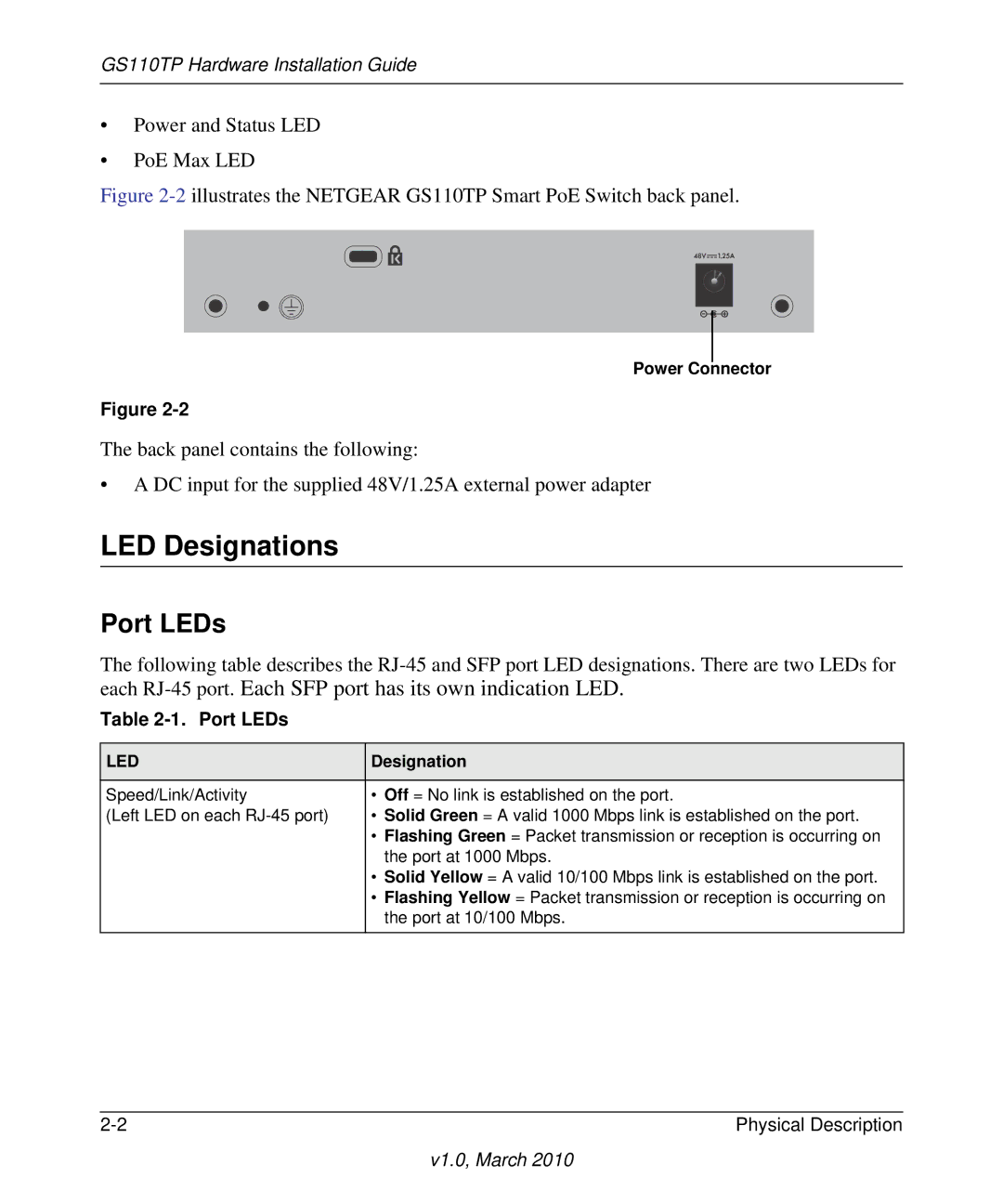
Figure 2-2 illustrates the NETGEAR GS110TP Smart PoE Switch back panel.
Power Connector
Figure
The back panel contains the following:
•A DC input for the supplied 48V/1.25A external power adapter
LED Designations
Port LEDs
The following table describes the
Table 2-1. Port LEDs
LED | Designation |
|
|
Speed/Link/Activity | • Off = No link is established on the port. |
(Left LED on each | • Solid Green = A valid 1000 Mbps link is established on the port. |
| • Flashing Green = Packet transmission or reception is occurring on |
| the port at 1000 Mbps. |
| • Solid Yellow = A valid 10/100 Mbps link is established on the port. |
| • Flashing Yellow = Packet transmission or reception is occurring on |
| the port at 10/100 Mbps. |
|
|
Physical Description |
v1.0, March 2010