NTI VEEMUX VIDEO MATRIX SWITCH
Connect RS232
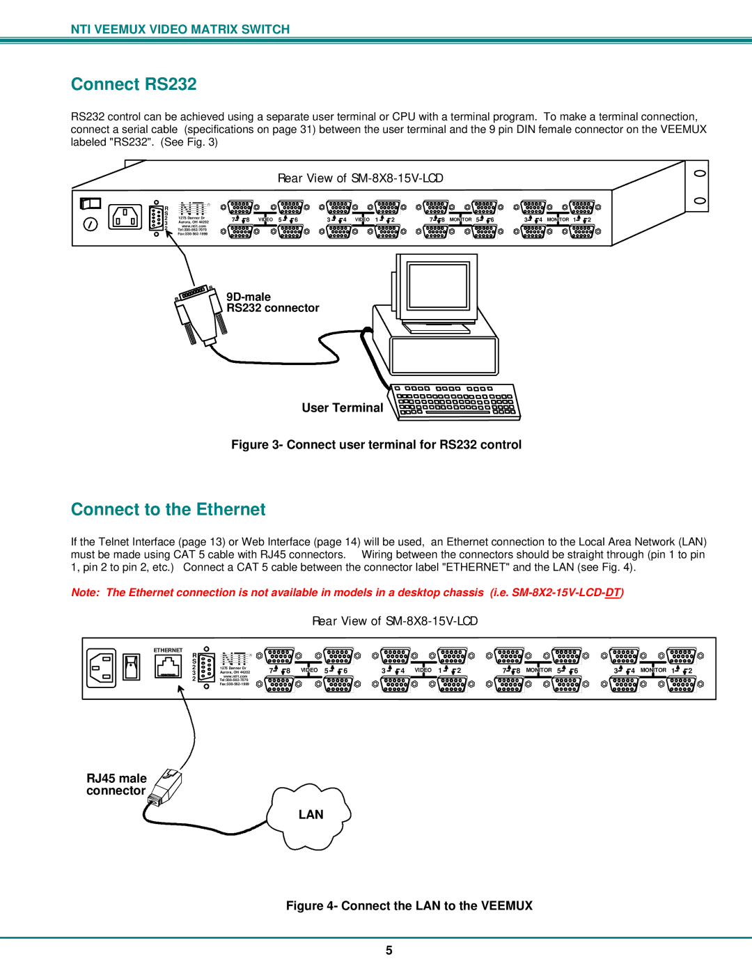
RS232 control can be achieved using a separate user terminal or CPU with a terminal program. To make a terminal connection, connect a serial cable (specifications on page 31) between the user terminal and the 9 pin DIN female connector on the VEEMUX labeled "RS232". (See Fig. 3)
S | NTI | R |
R |
|
|
2 | 1275 Danner Dr |
|
3 | Aurora, OH 44202 | |
2 | www.nti1.com |
|
| ||
|
|
| Rear View of |
|
| |||||
7 | 8 | VIDEO | 5 | 6 | 3 | 4 VIDEO 1 | 2 | 7 8 | MONITOR 5 | 6 |
3 | 4 | MONITOR | 1 | 2 |
9D-male
RS232 connector
VGA
Monitor
User Terminal ![]()
![]()
![]()
![]()
![]()
![]()
![]()
![]()
![]()
![]()
![]()
![]()
![]()
![]()
![]()
![]()
![]()
Figure 3- Connect user terminal for RS232 control
Connect to the Ethernet
If the Telnet Interface (page 13) or Web Interface (page 14) will be used, an Ethernet connection to the Local Area Network (LAN) must be made using CAT 5 cable with RJ45 connectors. Wiring between the connectors should be straight through (pin 1 to pin 1, pin 2 to pin 2, etc.) Connect a CAT 5 cable between the connector label "ETHERNET" and the LAN (see Fig. 4).
Note: The Ethernet connection is not available in models in a desktop chassis (i.e.
Rear View of SM-8X8-15V-LCD
ETHERNET | NTI | R |
|
|
|
|
|
S |
|
|
|
|
| ||
R |
|
|
|
|
|
| |
2 | 1275 Danner Dr |
| 7 | 8 | VIDEO | 5 | 6 |
3 | Aurora, OH 44202 | ||||||
www.nti1.com |
|
|
|
|
|
| |
2 |
|
|
|
|
|
| |
|
|
|
|
|
|
| |
3 | 4 | VIDEO | 1 | 2 | 7 | 8 | MONITOR | 5 | 6 | 3 | 4 | MONITOR | 1 | 2 |
RJ45 male
connector ![]()
LAN
Figure 4- Connect the LAN to the VEEMUX
5
