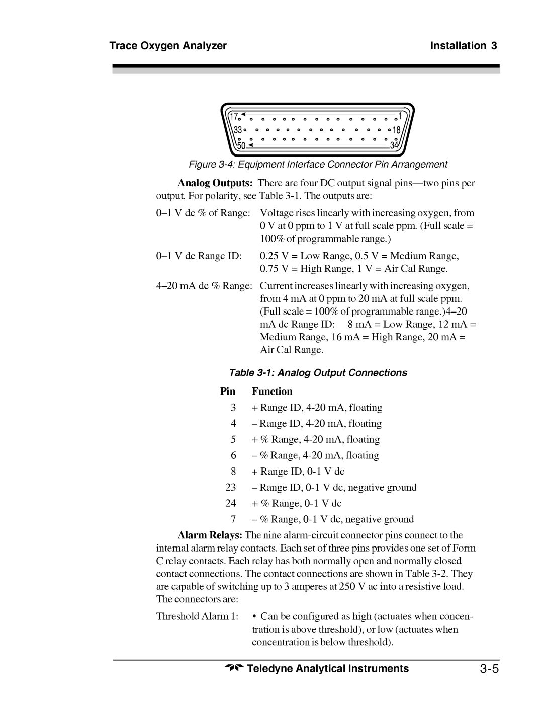
Figure 3-4: Equipment Interface Connector Pin Arrangement
Analog Outputs: There are four DC output signal pins—two pins per output. For polarity, see Table 3-1. The outputs are:
0–1 V dc % of Range: Voltage rises linearly with increasing oxygen, from 0 V at 0 ppm to 1 V at full scale ppm. (Full scale = 100% of programmable range.)
0–1 V dc Range ID: 0.25 V = Low Range, 0.5 V = Medium Range, 0.75 V = High Range, 1 V = Air Cal Range.
4–20 mA dc % Range: Current increases linearly with increasing oxygen, from 4 mA at 0 ppm to 20 mA at full scale ppm. (Full scale = 100% of programmable range.)4–20 mA dc Range ID: 8 mA = Low Range, 12 mA = Medium Range, 16 mA = High Range, 20 mA = Air Cal Range.
Table 3-1: Analog Output Connections
Pin Function
3+ Range ID, 4-20 mA, floating
4– Range ID, 4-20 mA, floating
5+ % Range, 4-20 mA, floating
6– % Range, 4-20 mA, floating
8+ Range ID, 0-1 V dc
23– Range ID, 0-1 V dc, negative ground
24+ % Range, 0-1 V dc
7 – % Range, 0-1 V dc, negative ground
Alarm Relays: The nine alarm-circuit connector pins connect to the internal alarm relay contacts. Each set of three pins provides one set of Form C relay contacts. Each relay has both normally open and normally closed contact connections. The contact connections are shown in Table 3-2. They are capable of switching up to 3 amperes at 250 V ac into a resistive load. The connectors are:
Threshold Alarm 1: • Can be configured as high (actuates when concen- tration is above threshold), or low (actuates when concentration is below threshold).
Teledyne Analytical Instruments | 3-5 |