Trace Oxygen Analyzer | Installation 3 | |
|
|
|
|
|
|
|
|
|
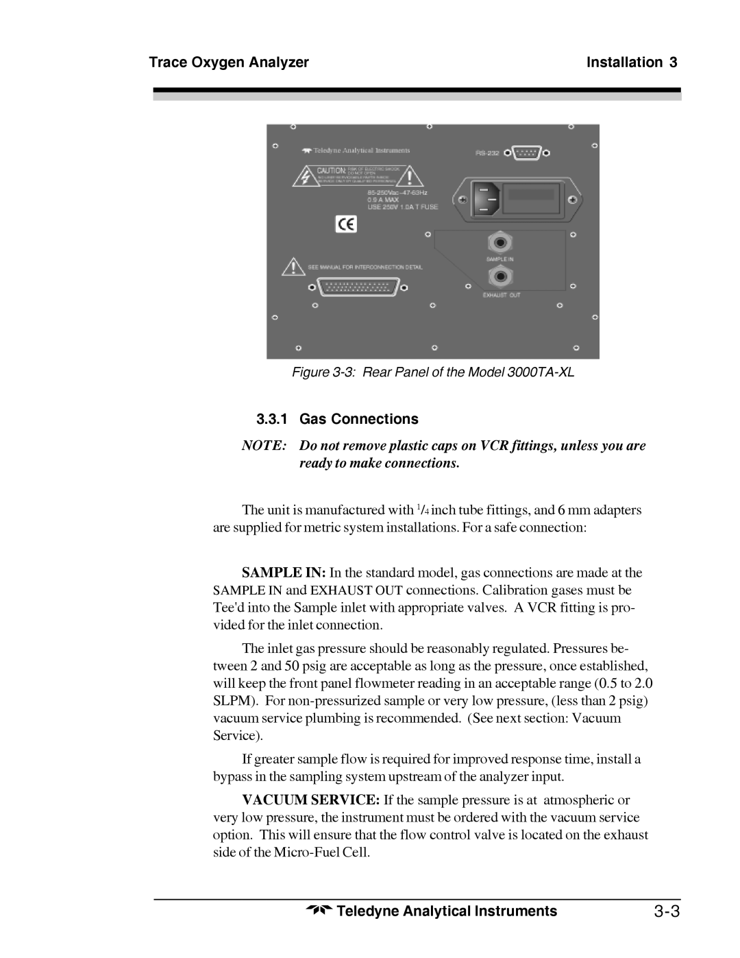
Figure 3-3: Rear Panel of the Model 3000TA-XL
3.3.1 Gas Connections
NOTE: Do not remove plastic caps on VCR fittings, unless you are ready to make connections.
The unit is manufactured with 1/4 inch tube fittings, and 6 mm adapters are supplied for metric system installations. For a safe connection:
SAMPLE IN: In the standard model, gas connections are made at the SAMPLE IN and EXHAUST OUT connections. Calibration gases must be Tee'd into the Sample inlet with appropriate valves. A VCR fitting is pro- vided for the inlet connection.
The inlet gas pressure should be reasonably regulated. Pressures be- tween 2 and 50 psig are acceptable as long as the pressure, once established, will keep the front panel flowmeter reading in an acceptable range (0.5 to 2.0 SLPM). For
If greater sample flow is required for improved response time, install a bypass in the sampling system upstream of the analyzer input.
VACUUM SERVICE: If the sample pressure is at atmospheric or very low pressure, the instrument must be ordered with the vacuum service option. This will ensure that the flow control valve is located on the exhaust side of the
Teledyne Analytical Instruments |