Trace Oxygen Analyzer | Introduction 1 | |
|
|
|
|
|
|
|
|
|
all the way in with a narrow gauge tool. Accessing the main circuit board requires unfastening rear panel screws and sliding the unit out of the case.
1.6Rear Panel (Equipment Interface)
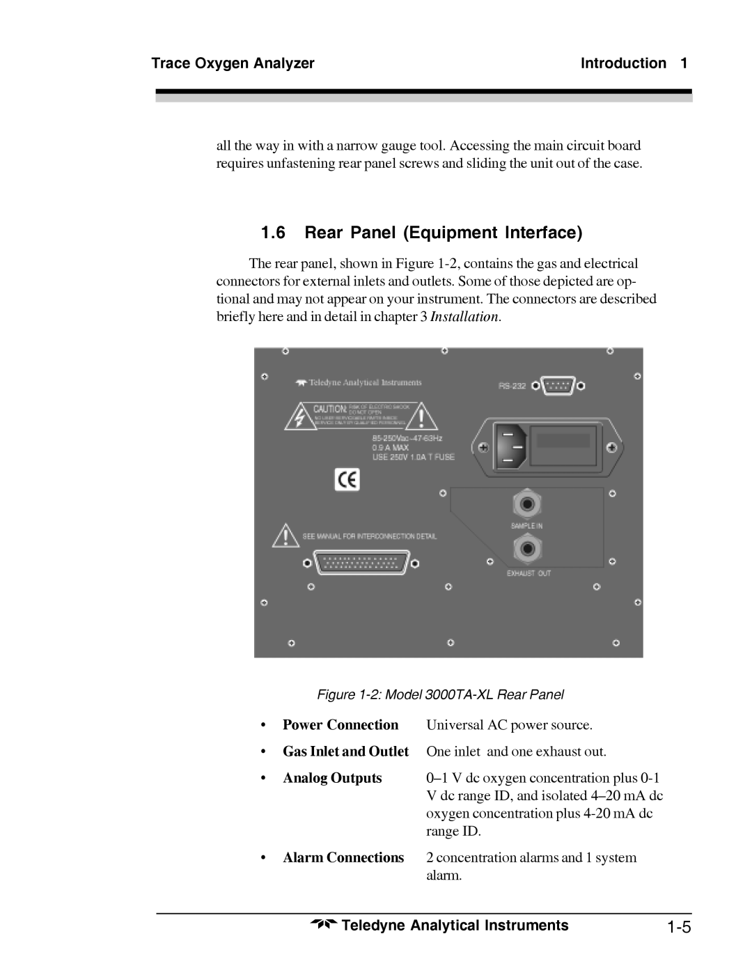
The rear panel, shown in Figure
Figure 1-2: Model 3000TA-XL Rear Panel
•Power Connection Universal AC power source.
•Gas Inlet and Outlet One inlet and one exhaust out.
• Analog Outputs | |
| V dc range ID, and isolated |
| oxygen concentration plus |
| range ID. |
•Alarm Connections 2 concentration alarms and 1 system alarm.
Teledyne Analytical Instruments |
