Indoor Pendant
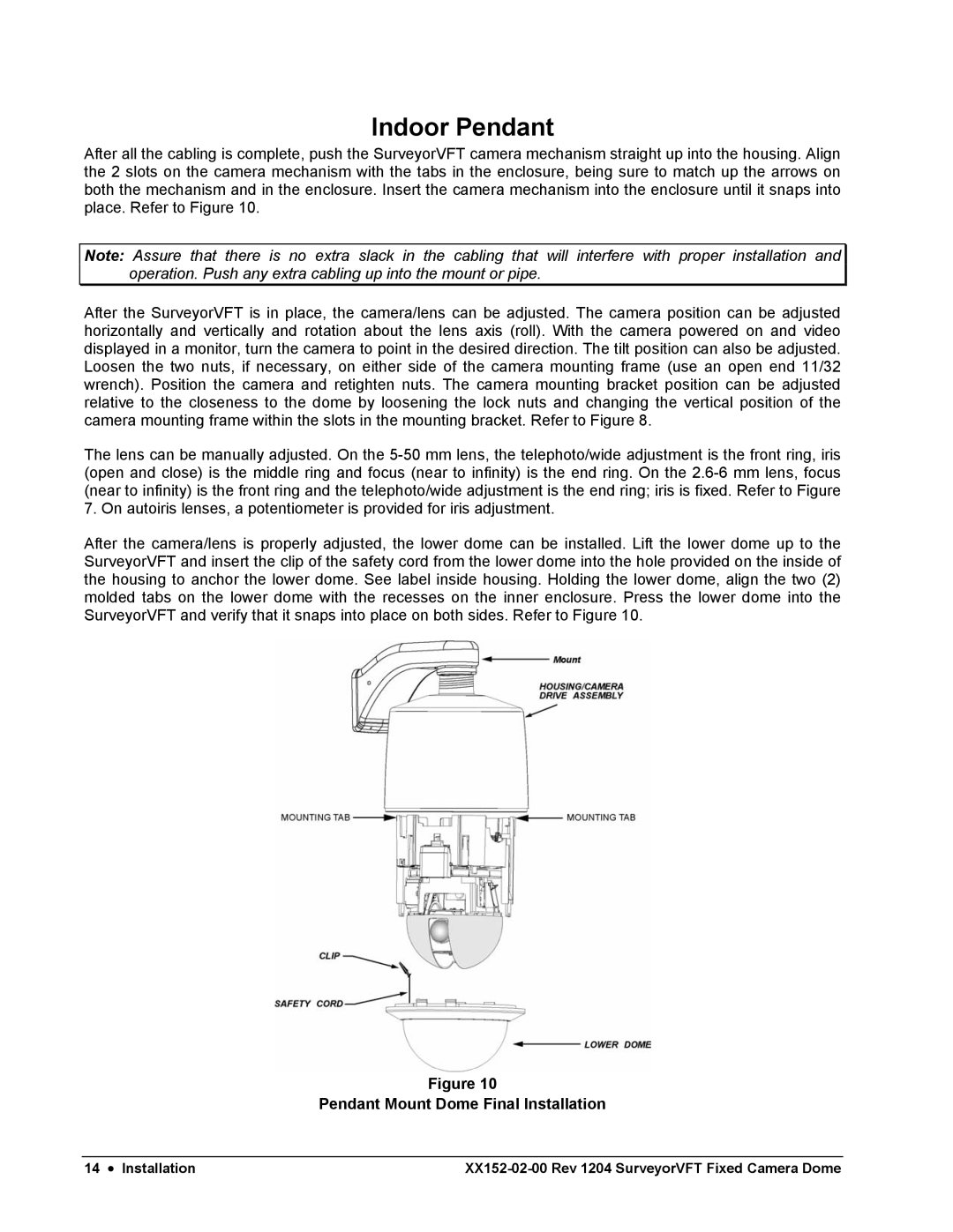
After all the cabling is complete, push the SurveyorVFT camera mechanism straight up into the housing. Align the 2 slots on the camera mechanism with the tabs in the enclosure, being sure to match up the arrows on both the mechanism and in the enclosure. Insert the camera mechanism into the enclosure until it snaps into place. Refer to Figure 10.
Note: Assure that there is no extra slack in the cabling that will interfere with proper installation and operation. Push any extra cabling up into the mount or pipe.
After the SurveyorVFT is in place, the camera/lens can be adjusted. The camera position can be adjusted horizontally and vertically and rotation about the lens axis (roll). With the camera powered on and video displayed in a monitor, turn the camera to point in the desired direction. The tilt position can also be adjusted. Loosen the two nuts, if necessary, on either side of the camera mounting frame (use an open end 11/32 wrench). Position the camera and retighten nuts. The camera mounting bracket position can be adjusted relative to the closeness to the dome by loosening the lock nuts and changing the vertical position of the camera mounting frame within the slots in the mounting bracket. Refer to Figure 8.
The lens can be manually adjusted. On the
After the camera/lens is properly adjusted, the lower dome can be installed. Lift the lower dome up to the SurveyorVFT and insert the clip of the safety cord from the lower dome into the hole provided on the inside of the housing to anchor the lower dome. See label inside housing. Holding the lower dome, align the two (2) molded tabs on the lower dome with the recesses on the inner enclosure. Press the lower dome into the SurveyorVFT and verify that it snaps into place on both sides. Refer to Figure 10.
Figure 10
Pendant Mount Dome Final Installation
14 • Installation |