3.Working above the ceiling, remove the enclosure top by loosening the 3 screws and lifting it off.
4.If cables are used without the use of flexible conduit:
a.Remove the conduit fitting by loosening the nut and sliding it out. Install the supplied strain relief fitting in its place and
b.Route approximately 12 in. (305 mm) of cables through the strain relief fitting. Tighten the two (2) strain relief fitting screws to compress the cables. Do not overtighten the screws and crush the cables.
4.If cables are channeled through flexible cable:
a.Route approximately 12 in. (305 mm) of conduit cables through the conduit fitting.
b.Insert the end of the flexible conduit pipe into the conduit fitting and tighten the clamp screw.
Continue with the section on Cable Connections.
Optional Independent Support
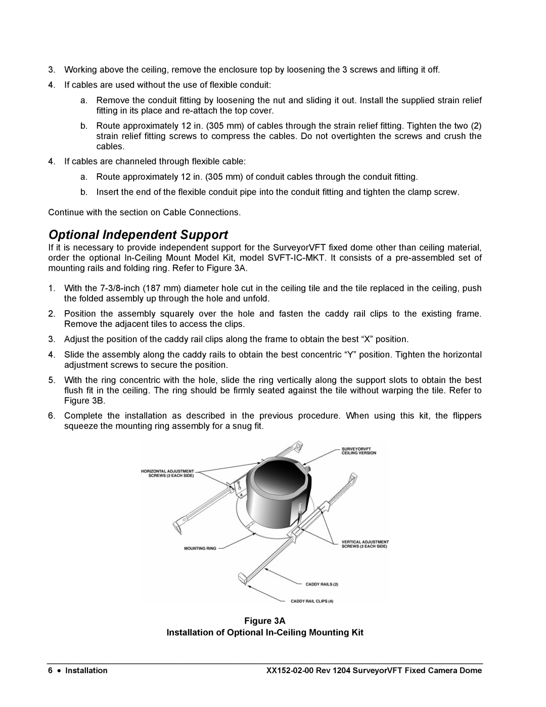
If it is necessary to provide independent support for the SurveyorVFT fixed dome other than ceiling material, order the optional
1.With the
2.Position the assembly squarely over the hole and fasten the caddy rail clips to the existing frame. Remove the adjacent tiles to access the clips.
3.Adjust the position of the caddy rail clips along the frame to obtain the best “X” position.
4.Slide the assembly along the caddy rails to obtain the best concentric “Y” position. Tighten the horizontal adjustment screws to secure the position.
5.With the ring concentric with the hole, slide the ring vertically along the support slots to obtain the best flush fit in the ceiling. The ring should be firmly seated against the tile without warping the tile. Refer to Figure 3B.
6.Complete the installation as described in the previous procedure. When using this kit, the flippers squeeze the mounting ring assembly for a snug fit.
Figure 3A
Installation of Optional In-Ceiling Mounting Kit
6 • Installation |
